PID Loop Operation
Maintenance
8–37
PID Loop Operation
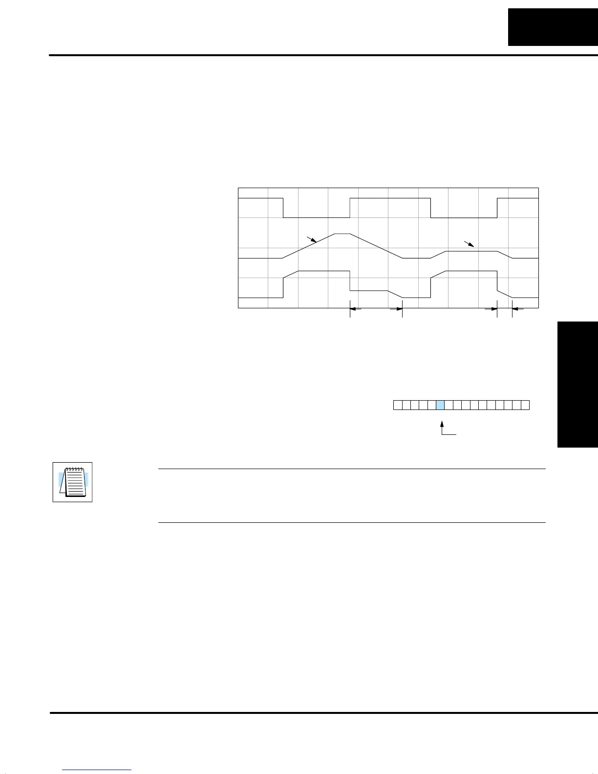
The term “reset windup” refers to an undesirable characteristic of integrator
behavior which occurs naturally under certain conditions. Refer to the figure below.
Suppose the PV signal becomes disconnected, and the PV value goes to zero.
While this is a serious loop fault, it is made worse by reset windup. Notice the bias
(reset) term keeps integrating normally during the PV disconnect, until its upper limit
is reached. When the PV signal returns, the bias value is saturated (windup) and
takes a long time to return to normal. The loop output consequently has an extended
recovery time. Until recovery, the output level is wrong and causes further problems.
PV
Output
0
Bias
Reset windup
Freeze bias enabled
Recovery time Recovery time
PV loss PV loss
In the second PV signal loss episode in the figure, the freeze bias feature is enabled.
It causes the bias value to freeze when the control output goes out of bounds. Much
of the reset windup is thus avoided, and the output recovery time is much less.
For most applications, the freeze bias
feature will work with the loop as
described above. You may enable the
feature using the DirectSOFT32 PID View
setup dialog, or set bit 10 of PID Mode 1
Setting word as shown to the right.
PID Mode 1 Setting V+00
013456789101112131415 2Bit
Bias freeze
select
NOTE: The bias freeze feature stops the bias term from changing when the control
output reaches the end of the data range. If you have set limits on the control output
other than the range (i.e, 0–4095 for a unipolar/12bit loop), the bias term still uses the
end of range for the stopping point and bias freeze will not work.
In the feedforward method discussed later in this chapter, ladder logic writes directly
to the bias term value. However, there is no conflict with the freeze bias feature,
because bias term writes due to feedforward are relatively infrequent when in use.
Bias Freeze