Installation, Wiring,
and Specifications
2–26
Installation, Wiring, and Specifications
Wiring Diagrams and Specifications
The remainder of this chapter dedicates two pages to each of the eight versions of
DL05 Micro PLCs. Each section contains a basic wiring diagram, equivalent I/O
circuits, and specification tables. Please refer to the section which describes the
particular DL05 version used in your application.
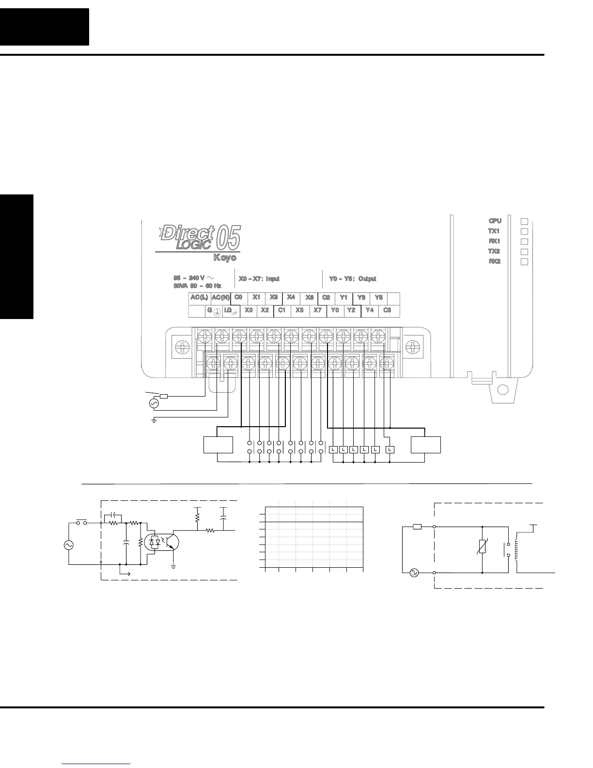
The D0–05AR Micro PLC features eight AC inputs and six relay contact outputs. The
following diagram shows a typical field wiring example. The AC external power
connection uses four terminals at the left as shown.
Output Point Wiring
Ground
Neutral
Line
Power
Input Wiring
Input Point Wiring
AC or DC
Supply
Equivalent Input Circuit
Optical
Common
Input
+V
Isolator
To other circuits in bank
AC
Supply
Fuse
or
C.B.
Derating Chart for Relay Outputs
0
2
4
6
Points
0102030405055
Ambient Temperature (°C/°F)
32 50 68 86 104 122 131
C°
F°
Y0 – Y5
2 A
+V
To LED
Equivalent Output Circuit
COM
OUTPUT
To LED
Internal module circuitry
6–240 VAC
L
6–27 VDC
Line
+V
The eight AC input channels use terminals in the middle of the connector. Inputs are
organized into two banks of four. Each bank has a common terminal. The wiring
example above shows all commons connected together, but separate supplies and
common circuits may be used. The equivalent input circuit shows one channel of a
typical bank.
D0–05AR
I/O Wiring Diagram