Installation, Wiring,
and Specifications
2–36
Installation, Wiring, and Specifications
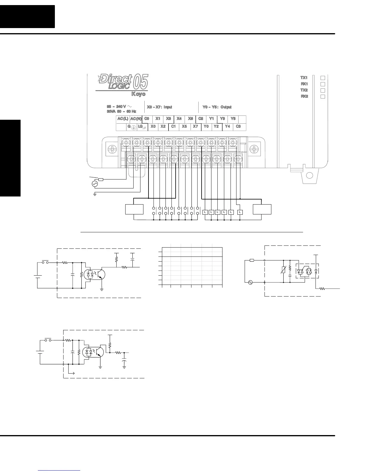
The D0–05DA Micro PLC features eight DC inputs and six AC outputs. The following
diagram shows a typical field wiring example. The AC external power connection
uses four terminals at the left as shown.
Output Point Wiring
Ground
Neutral
Line
Power
Input Wiring
Input Point Wiring
AC
Supply
DC
Supply
Fuse
or
C.B.
Derating Chart for AC Outputs
0
2
4
6
Points
0102030405055
Ambient Temperature (°C/°F)
32 50 68 86 104 122 131
C°
F°
Y0 – Y5
0.5 A
Equivalent Output Circuit
Optical
COM
Isolator
OUTPUT
To LED
Internal module circuitry
17–240
L
VAC
Line
+V
Equivalent Circuit,
Standard Inputs (X3 – X7)
Optical
Common
Input
+V
Isolator
+V
To LED
+
–
The eight DC input channels use terminals in the middle
of the connector. Inputs are organized into two banks of
four. Each bank has an isolated common terminal, and
may be wired as sinking or sourcing inputs. The wiring
example above shows all commons connected together,
but separate supplies and common circuits may be used.
The equivalent circuit for standard inputs is shown
above, and the high-speed input circuit is shown to the
left.
Input
Equivalent Circuit, High-
Speed Inputs (X0 – X2)
Optical
Common
Isolator
+
–
To LED
To all other output circuits
+V
The six output channels use terminals on the right side of the connector. Outputs are
organized into two banks of three triac switches. Each bank has a common terminal.
The wiring example above shows all commons connected together, but separate
supplies and common circuits may be used. The equivalent output circuit shows one
channel of a typical bank.
D0–05DA
I/O Wiring Diagram