PID Loop Operation
Maintenance
8–27
PID Loop Operation
In many batch process applications, sensors or actuators interface to DL05 analog
modules using 4–20 mA signals. This signal type has a built-in 20% offset, because
the zero-point is a 4 mA instead of 0 mA. However, remember the analog modules
convert the signals into data and remove the offset at the same time. For example, a
4–20 mA signal is often converted to 0000 – 0FFF hex, or 0 to 4095 decimal. In this
case, all you need to do is choose 12-bit unipolar data format, and make sure the
ladder program copies the data appropriately between the loop table and the analog
modules.
S PV Offset – In the event you have a PV value with a 20% offset, convert
it to zero–offset by subtracting 20% of the top of its range, and multiply
by1.25.
S Control Output – In the event the Control Output is going to a device
with 20% offset, all you need to do is have the ladder program write a
value equivalent to the offset to the integrator register (V+04), before
transitioning from Manual to Auto mode. The loop will then see this
offset as a part of the process, taking care of it for you automatically.
The Setpoint in loop table location V+02 represents the desired value of the process
variable. After selecting the data format for these variables, you can set limits on the
range of SP values which the loop calculation will use. Many loops have two or more
possible sources writing the Setpoint at various times, and the limits you set will help
safeguard the process from the effects of a bad SP value.
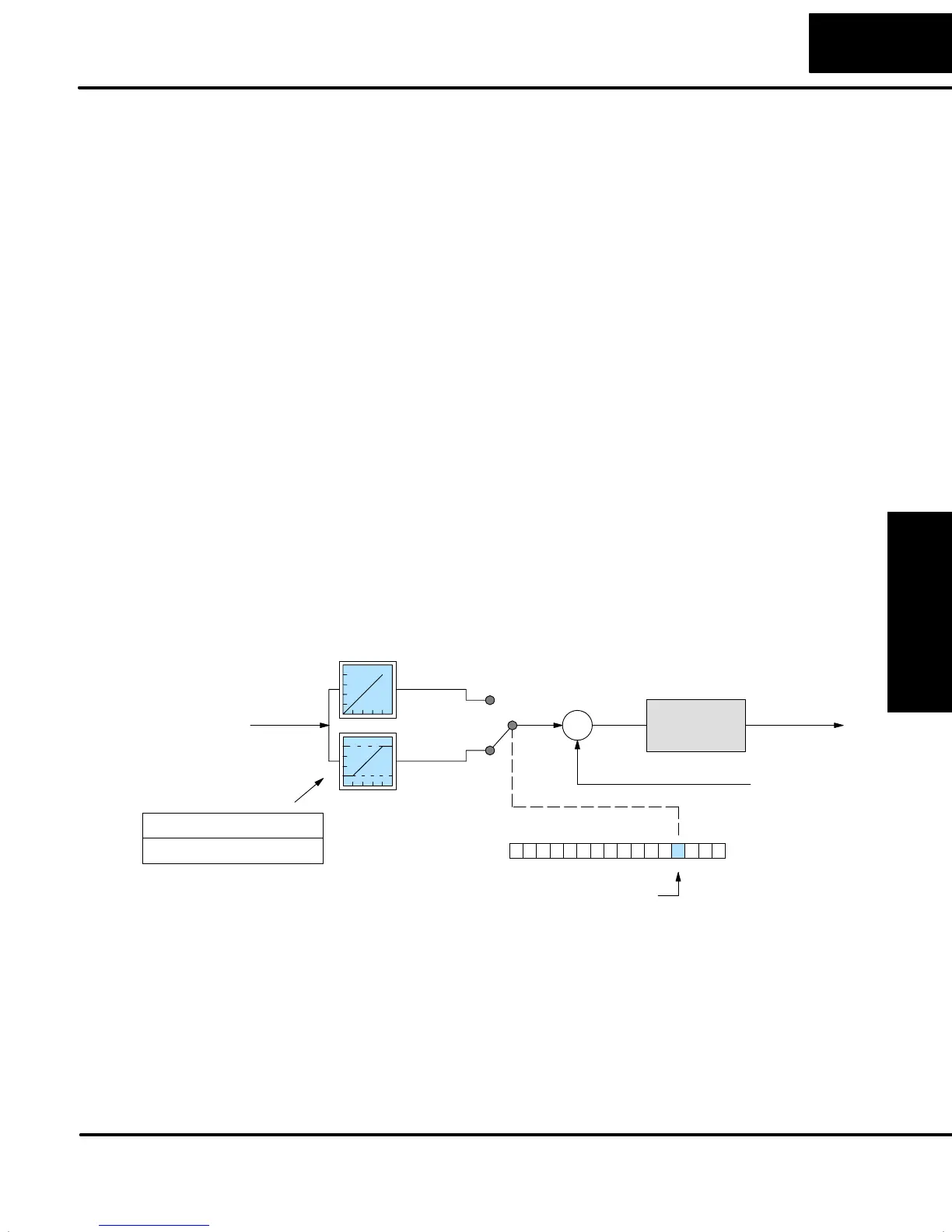
In the figure below, the SP has a selectable limit function, enabled by PID Mode 2
Setting V+01 word, bit 3. If enabled, then locations V+26 and V+27 determine the
lower and upper SP limits, respectively. The loop calculation applies this limit
internally, so it is always possible to write any value to V+02.
Process Variable (PV)
Loop
Calculation
S
+
–
Control
Output
PID Mode 2 Setting V+01
013456789101112131415 2Bit
Setpoint
No
Limits
With
Limits
0
1
SP Limits enable
Loop Table
V+26 SP Lower LimitXXXX
V+27 SP Upper LimitXXXX
The loop calculation checks these SP upper and lower limits before each
calculation. This means ladder logic can change the limit settings while a process is
in progress, allowing you to keep a tighter guard band on the SP input value.
Handling
Data Offsets
Setpoint (SP)
Limits