Drum Instruction
Programming
6–3
Drum Instruction Programming
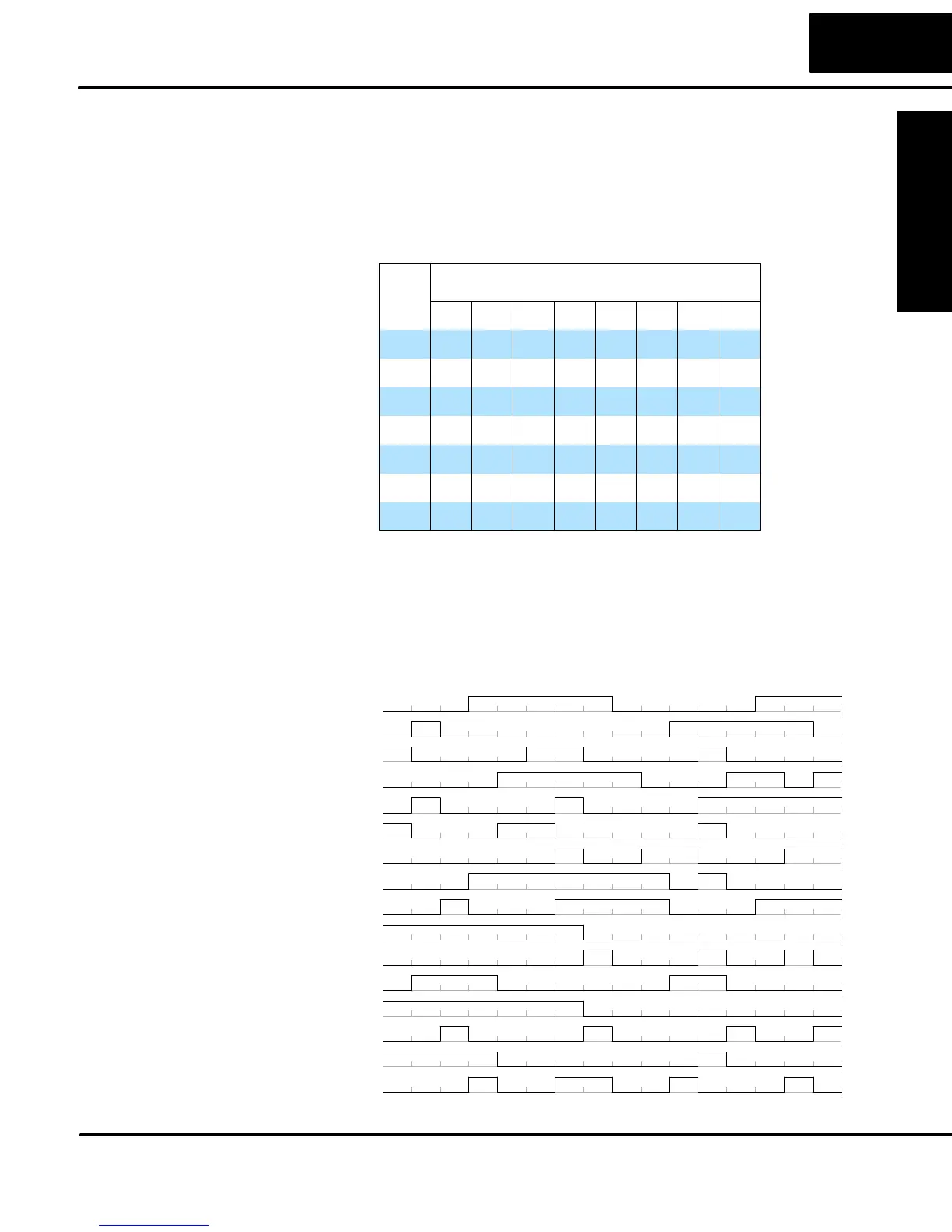
For editing purposes, the electronic drum is presented in chart form in DirectSOFT
and in this manual. Imagine slicing the surface of a hollow drum cylinder between
two rows of pegs, then pressing it flat. Now you can view the drum as a chart as
shown below. Each row represents a step, numbered 1 through 16. Each column
represents an output, numbered 0 through 15 (to match word bit numbering). The
solid circles in the chart represent pegs (On state) in the mechanical drum, and the
open circles are empty peg sites (Off state).
1
STEP
2
3
4
5
6
7
8
9
10
11
12
13
14
15
16
f
F
f
FffFfffFffFff
fFfFFfFffffFffFf
f
FFFFfFFffffffff
FFfFFfFfFffffffF
F
f
fFffFFFFfFFFfF
FfFffFfFFfffFffF
ff
fFffFfFfFfFffF
fffFffFfFfFfFFfF
ff
fffffFFfffFfff
fffffffFFFffffff
F
f
ffFffffFffffFf
fFffFFffFfFFfF
F
f
ff
FffffffffFFfFf
fffffffFfffFFfFF
F
f
fffFfFfFfFffFF
ffFffffFfFfFFffF
1 2 3 4 5 6 7 8 9101112131415 0
OUTPUTS
The mechanical drum sequencer derives its name from sequences of control
changes on its electrical outputs. The following figure shows the sequence of On/Off
controls generated by the drum pattern above. Compare the two, and you will find
that they are equivalent! If you can see their equivalence, you are well on your way to
understanding drum instruction operation.
0
0
1
1
0
1
2
0
1
3
0
1
4
0
1
5
0
1
6
0
1
7
0
1
8
0
1
9
0
1
10
0
1
11
0
1
12
0
1
13
0
1
14
0
1
15
0
1
Output
12345678910111213141516
Step
Drum Chart
Representation
Output Sequences