PID Loop Operation
Maintenance
and Troubleshooting
8–2
PID Loop Operation
DL05 PID Loop Features
The DL05 process loop control offers a sophisticated set of features to address
many application needs. The main features are:
S Up to 4 loops, individual programmable sample rates
S Manual/ Automatic/Cascaded loop capability available
S Two types of bumpless transfer available
S Full-featured alarms
S Ramp/soak generator with up to 16 segments
S Auto Tuning
The DL05 CPU has process control loop capability in addition to ladder program
execution. You can select and configure up to four loops. All sensor and actuator
wiring connects directly to DL05 analog modules. All process variables, gain values,
alarm levels, etc., associated with each loop reside in a Loop Variable Table in the
CPU. The DL05 CPU reads process variable (PV) inputs during each scan. Then it
makes PID loop calculations during a dedicated time slice on each PLC scan,
updating the control output value. The control loops use a
Proportional-Integral-Derivative (PID) algorithm to generate the control output. This
chapter describes how the loops operate, and what you must do to configure and
tune the loops.
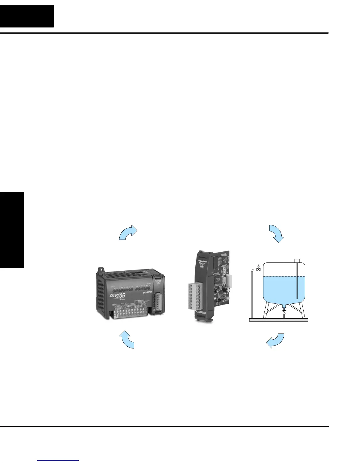
DL05
Manufacturing Process
PID Loop Calculations
Analog Output
Analog Input
The best tool for configuring loops in the DL05 is the DirectSOFT32 programming
software, release 3.0c, or later. DirectSOFT32 uses dialog boxes to help you set up
the individual loops. After completing the setup, you can use DirectSOFT32’s PID
Trend View to tune each loop. The configuration and tuning selections you make are
stored in the DL05’s FLASH memory, which is retentive. The loop parameters also
may be saved to disk for recall later.
Main Features