Installation, Wiring,
and Specifications
2–24
Installation, Wiring, and Specifications
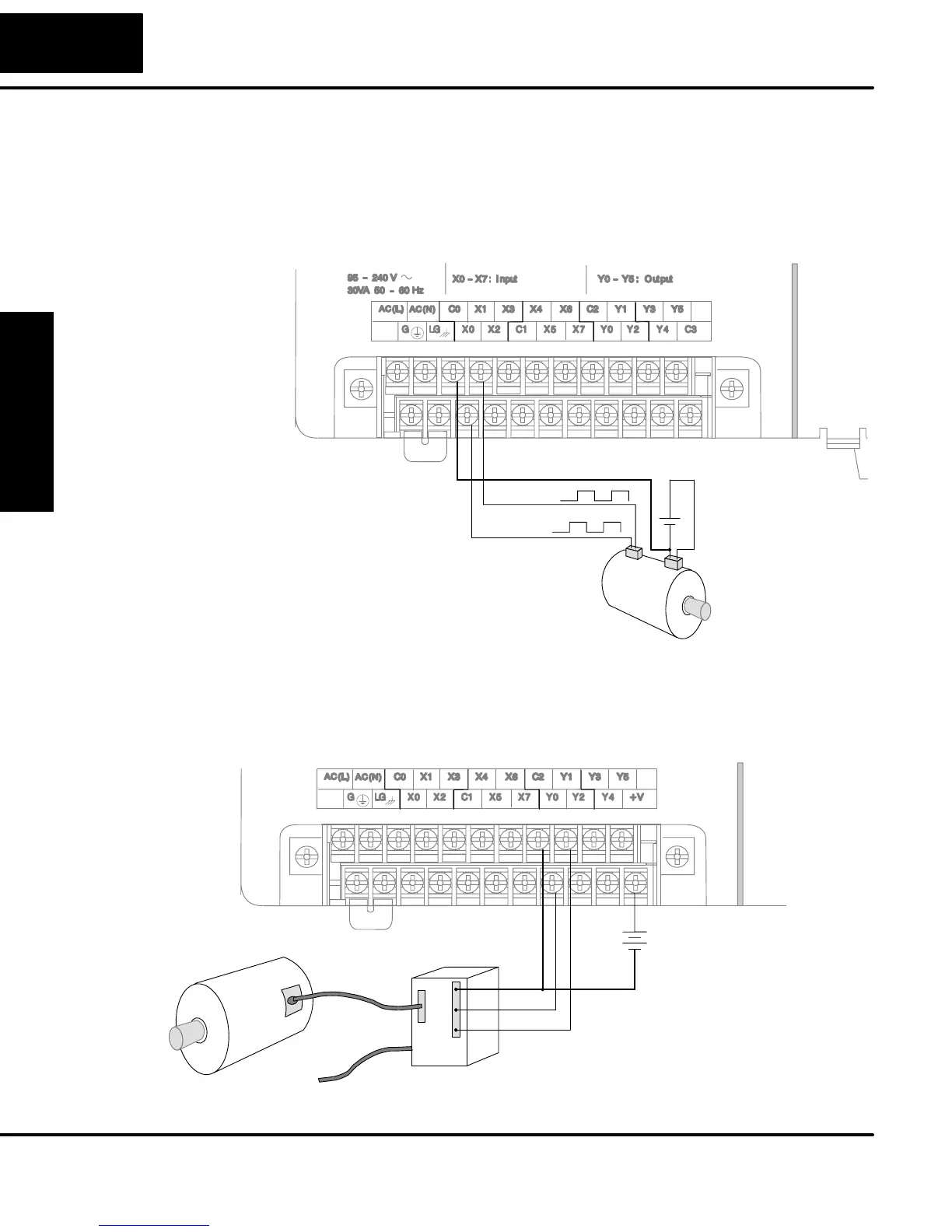
DL05 versions with DC type input or output points contain a dedicated High-Speed
I/O circuit (HSIO). The circuit configuration is programmable, and it processes select
I/O points independently from the CPU scan. Chapter 3 discusses the programming
options for HSIO. While the HSIO circuit has six modes, we show wiring diagrams for
two of the most popular modes in this chapter. The high-speed input interfaces to
points X0 – X2. Properly configured, the DL05 can count quadrature pulses at up to
5 kHz from an incremental encoder as shown below.
Encoder Input Wiring
+
–
12 – 24 VDC
Phase A
Phase B
Encoder
Signal Common
DL05 versions with DC type output points can use the High Speed I/O Pulse Output
feature. It can generate high-speed pulses for specialized control such as stepper
motor / intelligent drive systems. Output Y0 and Y1 can generate pulse and direction
signals, or it can generate CCW and CW pulse signals respectively. See Chapter 3
on high-speed input and pulse output options.
Signal Common
Motor Amplifier
Pulse Output Wiring
Power Input
+24 VDC
Pulse
Direction
+
–
High-Speed I/O
Wiring Methods