PID Loop Operation
Maintenance
and Troubleshooting
8–12
PID Loop Operation
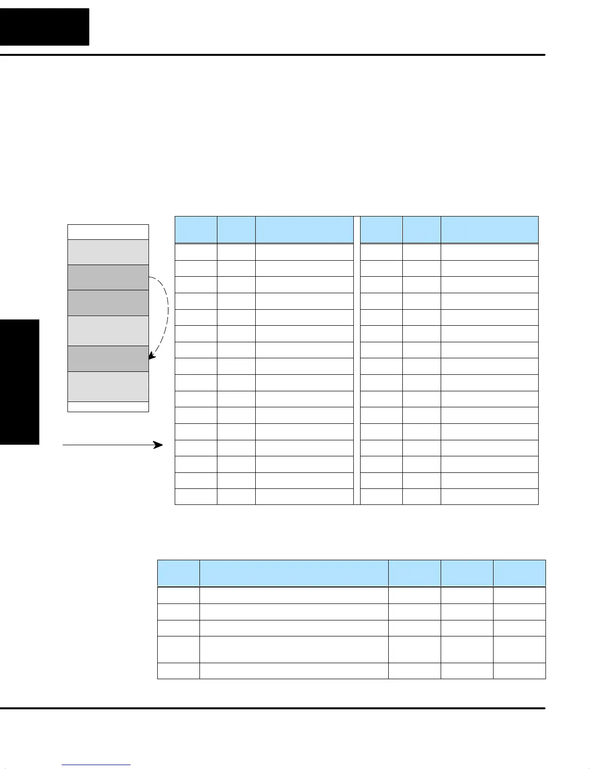
Each loop that you configure has the option of using a built-in Ramp/Soak generator
dedicated to that loop. This feature generates SP values that follow a profile. To use
the Ramp Soak feature, you must program a separate table of 32 words with
appropriate values. A DirectSOFT32 dialog box makes this easy to do.
In the loop table, the Ramp / Soak Table Pointer at Addr+34 must point to the start of
the ramp/soak data for that loop. This may be anywhere in user memory, and does
not have to adjoin to the Loop Parameter table, as shown to the left. Each R/S table
requires 32 words, regardless of the number of segments programmed.
The ramp/soak table parameters are defined in the table below. Further details are in
the section on Ramp / Soak Operation in this chapter.
Addr
Offset
Step Description Addr
Offset
Step Description
+ 00 1 Ramp End SP Value + 20 9 Ramp End SP Value
+ 01 1 Ramp Slope + 21 9 Ramp Slope
+ 02 2 Soak Duration + 22 10 Soak Duration
+ 03 2 Soak PV Deviation + 23 10 Soak PV Deviation
+ 04 3 Ramp End SP Value + 24 11 Ramp End SP Value
+ 05 3 Ramp Slope + 25 11 Ramp Slope
+ 06 4 Soak Duration + 26 12 Soak Duration
+ 07 4 Soak PV Deviation + 27 12 Soak PV Deviation
+ 10 5 Ramp End SP Value + 30 13 Ramp End SP Value
+ 11 5 Ramp Slope + 31 13 Ramp Slope
+ 12 6 Soak Duration + 32 14 Soak Duration
+ 13 6 Soak PV Deviation + 33 14 Soak PV Deviation
+ 14 7 Ramp End SP Value + 34 15 Ramp End SP Value
+ 15 7 Ramp Slope + 35 15 Ramp Slope
+ 16 8 Soak Duration + 36 16 Soak Duration
+ 17 8 Soak PV Deviation + 37 16 Soak PV Deviation
The individual bit definitions of the Ramp / Soak Table Programming Error Flags
word (Addr+35) is listed in the following table. Further details are given in the PID
Loop Mode section and in the PV Alarm section later in this chapter.
Bit R/S Error Flag Bit Description Read/
Write
Bit=0 Bit=1
0 Starting Addr out of lower V-memory range read – Error
1 Starting Addr out of upper V-memory range read – Error
2–3 Reserved for Future Use – – –
4 Starting Addr in System Parameter
V-memory Range
read – Error
5–15 Reserved for Future Use – – –
Ramp/Soak
Table Location
(Addr + 34)
V–Memory Space
User Data
LOOP #1
V2000
32 words
LOOP #2
32 words
V2037
Ramp/Soak #1
32 words
V3000
V2034 = 3000 Octal
Pointer to R/S table
Ramp/Soak Table
Programming Error
Flags
(Addr + 35)