High-Speed Input and
Pulse Output Features
3–26
High-speed Input and Pulse Output Features
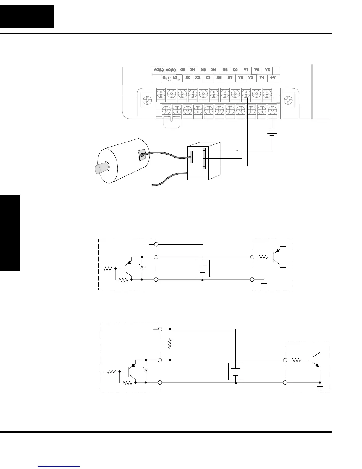
The generalized wiring diagram below shows pulse outputs Y0 and Y1 connected to
the drive amplifier inputs of a motion control system.
Signal Common
Motor Amplifier
Pulse Output Wiring
Power Input
+24 VDC
Pulse
Direction
+
–
The pulse signals from Y0 and Y1 outputs will typically go to drive input circuits as
shown above. Remember that the DL05’s DC outputs are sinking-only. It will be
helpful to locate equivalent circuit schematics of the drive amplifier. The following
diagram shows how to interface to a sourcing drive input circuit.
Drive Input
Output
Ground
Input
Common
+V
Y0, Y1 Pulse Output
+DC pwr
+
–
(sourcing)
(sinking)
Power
The following circuit shows how to interface to a sinking drive input using a pullup
resistor. Please refer to Chapter 2 to learn how to calculate and install R
pullup.
Drive Input
Output
Ground
Input
Common
Y0, Y1 Pulse Output
+DC pwr
+
–
(sourcing)
(sinking)
Power
(sinking)
pullup
Supply
R
input
R
Wiring Diagram
Interfacing to
Drive Inputs