High-Speed Input and
Pulse Output Features
3–34
High-speed Input and Pulse Output Features
Registration Profile Operation
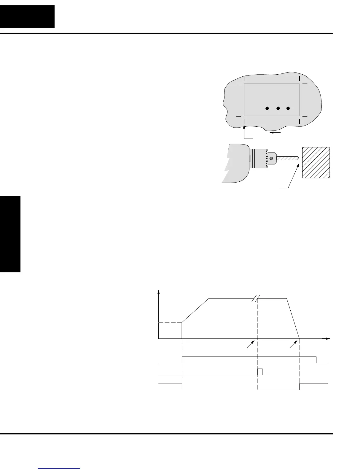
1. In a typical application shown to the
right, product material in work moves past
a work tool such as a drill. Registration
marks on the scrap area of the work-piece
allow a machine tool to register its position
relative to the rectangle, to drill properly.
2. In other examples of registration, the
work piece is stationary and the tool
moves. A drill bit may approach the
surface of a part in work, preparing to drill
a hole of precise depth. However, the drill
bit length gradually decreases due to tool
wear. A method to overcome this is to
detect the moment of contact with the part
surface on each drill, moving the bit into
the part a constant distance after contact.
Detect contact
Finished part area
Scrap
Area
Registration marks
direction of motion
3. The home search move allows a motion system to calibrate its position on
startup. In this case, the positioning system makes an indefinite move and waits for
the load to pass by a home limit switch. This creates an interrupt at the moment when
the load is in a known position. We then stop motion and preload the position value
with a number which equates to the physical “home position”.
The registration profile begins with only velocity control. When an interrupt pulse
occurs on physical input X2, the starting position is declared to be the present count
(current load position). The velocity control switches to position control, moving the
load to the target position. Note that the minimum starting velocity is 40 pps. This
instantaneous velocity accommodates stepper motors that can stall at low speeds.
Registration Profile
Time
Accel Decel
Velocity
Start
position
Target
position
Target Velocity
Starting
Velocity
Start
External Interrupt
Y0
X2
Profile Complete SP104
The time line of signal traces below the profile indicates the order of events. The
CPU uses logical output Y0 to start the profile. Immediately the HSIO turns off the
Profile Complete signal (SP104), so the ladder program can monitor the move’s
completion by sensing the signal’s on state.
Registration
Applications