High-Speed Input and
Pulse Output Features
3–10
High-speed Input and Pulse Output Features
The preset values occupy two data words each. They can range in value from 0000
0000 to 9999 9999, just like the high-speed counter value. All 24 values are absolute
values, meaning that each one is an offset from the counter zero value.
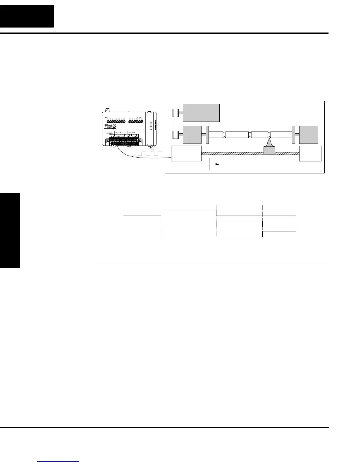
The preset values must be individually derived for each application. In the industrial
lathe diagram below, the PLC monitors the position of the lead screw by counting
pulses. At points A, B, and C along the linear travel, the cutter head pushes into the
work material and cuts a groove.
PLC
Industrial Lathe
Start
ABC
Counter
Device
X0, counter clock
Motor
The timing diagram below shows the duration of each equal relay contact closure.
Each contact remains on until the next one closes. All go off when the counter resets.
Equal Relays
SP540
SP541
SP542
ABC
NOTE: Each successive preset must be two numbers greater than the previous
preset value. In the industrial lathe example, B>A+1 and C>B+1.
The configurable discrete input options for High-Speed Counter Mode are listed in
the table below. Input X0 is dedicated for the counter clock input. Input X1 can be a
normal or filtered input. The section on Mode 60 operation at the end of this chapter
describes programming the filter time constants. Input X2 can be configured as the
counter reset, with or without the interrupt option. The interrupt option allows the
reset input (X2) to cause an interrupt like presets do, but there is no SP relay contact
closure (instead, X2 will be on during the interrupt routine, for 1 scan). Or finally, X2
may be left simply as a filtered input.
Calculating Your
Preset Values
X Input
Configuration