PID Loop Operation
Maintenance
and Troubleshooting
8–46
PID Loop Operation
The algorithm which the built-in filter follows is:
y
i
= k (x
i
– y
i–1
) + y
i–1
y
i
is the current output of the filter
x
i
is the current input to the filter
y
i–1
is the previous output of the filter
k is the PV Analog Input Filter Factor
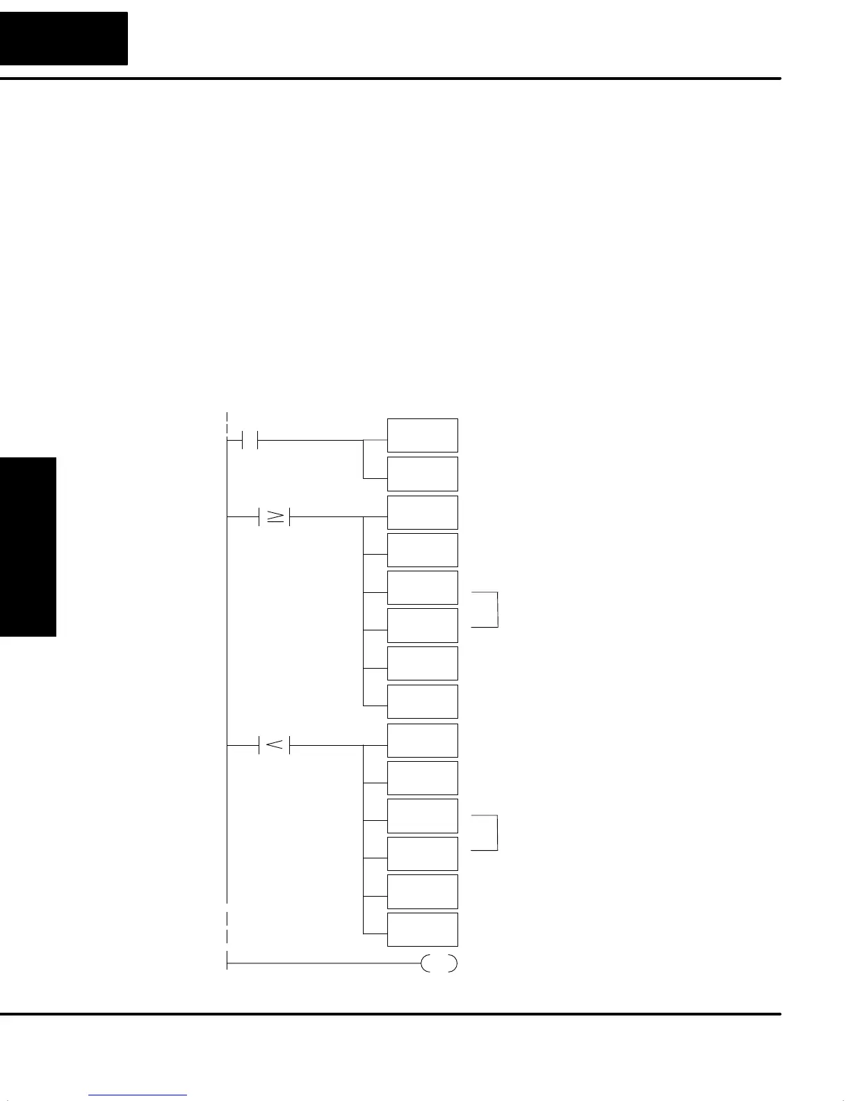
A similar algorithm can be built in your ladder program. Your analog inputs can be
filtered effectively using either method. The following programming example
describes the ladder logic you will need. Be sure to change the example memory
locations to those that fit your application.
Filtering can induce a 1 part in 1000 error in your output because of “rounding.” If
your process cannot tolerate a 1 part in 1000 error, do not use filtering. Because of
the rounding error, you should not use zero or full scale as alarm points. Additionally,
the smaller the filter constant the greater the smoothing effect, but the slower the
response time. Be sure a slower response is acceptable in controlling your process.
SP1
LD
K2
Output the constant to a convenient memory location that
is not in use.
If the raw analog input (V2200 in our example) is greater
than or equal to the current PV value in the PID Loop Table
(V2003), load the raw analog input into the accumulator.
Subtract the raw analog input the from Loop Table PV
value.
END
END coil marks the end of the main program.
Add the adjusted difference (between the raw analog input
and the PV) back to the analog input value.
If the raw analog input is less than the current PV
value in the PID Loop Table (V2003), load the current
PV value into the accumulator.
Load the filter constant into the accumulator. To mimick
the built-in filter, use values between 1 and 10. This is
equivalent to the 0.1 to 1.0 range of the built-in filter.
OUT
V1400
Add the adjusted difference (between the raw analog
input and the PV) back to the PV.
SUB
V2200
MUL
V1400
DIV
K10
V2200
LD
V2003
ADD
V2200
OUT
V2003
V2003
SUB
V2003
MUL
V1400
DIV
K10
V2200
LD
V2200
ADD
V2003
OUT
V2003
V2003
Subtract the Loop Table PV value from the raw
analog input.
The MUL and DIV instructions have the
combined effect of multiplying by a decimal
number between 0.1 and 1.0.
The MUL and DIV instructions have the
combined effect of multiplying by a decimal
number between 0.1 and 1.0.
Replace the previous Loop Table PV value with the
new filtered analog value in the Loop Table.
Replace the previous Loop Table PV value with the
new filtered analog value in the Loop Table.
Creating an
Analog Filter in
Ladder Logic