RLL PLUS
Stage Programming
7–10
RLL
PLUS
Stage Programming
Stage Program Example: A Garage Door Opener
In this next stage programming example
we’ll create a garage door opener
controller. Hopefully most readers are
familiar with this application, and we can
have fun besides!
The first step we must take is to describe
how the door opener works. We will start
by achieving the basic operation, waiting
to add extra features later. Stage
programs are very easy to modify.
Our garage door controller has a motor
which raises or lowers the door on
command. The garage owner pushes and
releases a momentary pushbutton once to
raise the door. After the door is up, another
push-release cycle will lower the door.
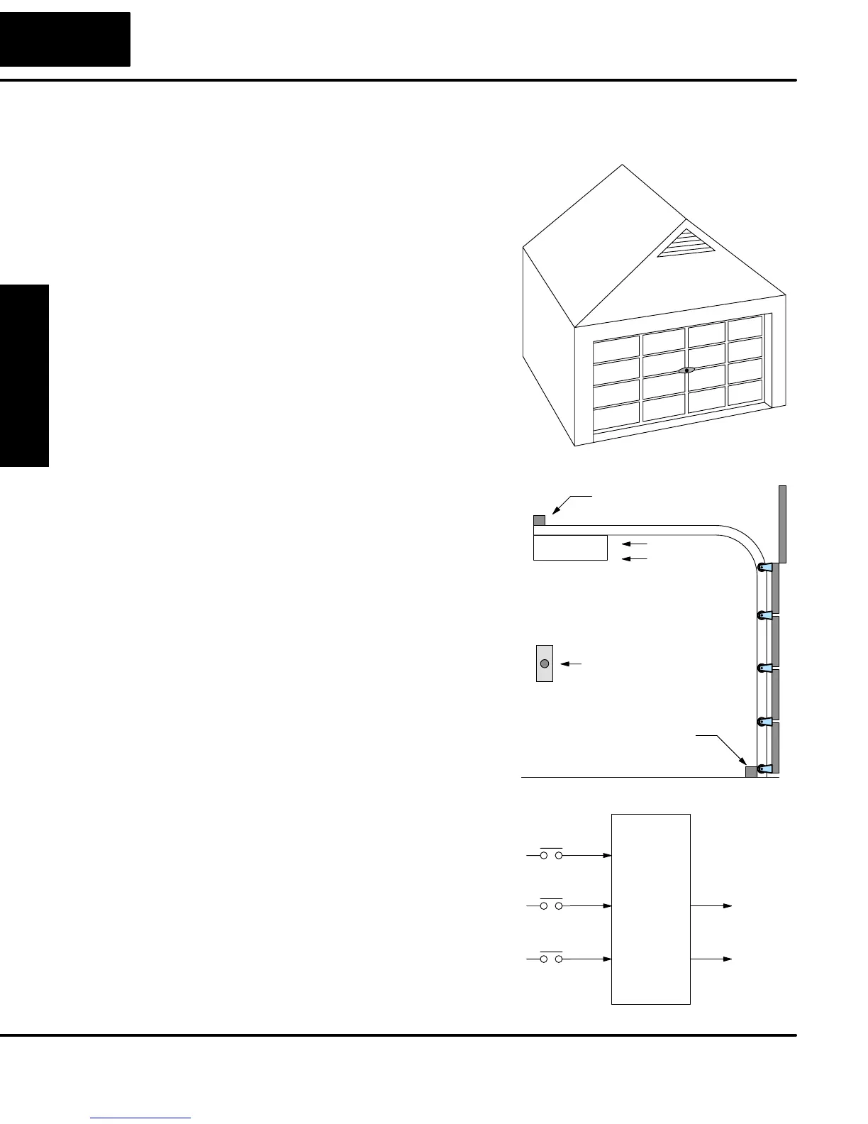
In order to identify the inputs and outputs
of the system, it’s sometimes helpful to
sketch its main components, as shown in
the door side view to the right. The door
has an up limit and a down limit switch.
Each limit switch closes only when the
door has reach the end of travel in the
corresponding direction. In the middle of
travel, neither limit switch is closed.
The motor has two command inputs: raise
and lower. When neither input is active,
the motor is stopped.
The door command is just a simple
pushbutton. Whether wall-mounted as
shown, or a radio-remote control, all door
control commands logical OR together as
one pair of switch contacts.
Down limit switch
Up limit switch
Motor
Raise
Lower
Door
Command
The block diagram of the controller is
shown to the right. Input X0 is from the
pushbutton door control. Input X1
energizes when the door reaches the full
up position. Input X2 energizes when the
door reaches the full down position. When
the door is positioned between fully up or
down, both limit switches are open.
The controller has two outputs to drive the
motor. Y1 is the up (raise the door)
command, and Y2 is the down (lower the
door) command.
Ladder
Program
Inputs Outputs
Toggle
X0
Y1
To motor:
Raise
Y2
Lower
Up limit
X1
Down limit
X2
Garage Door
Opener Example
Draw the Block
Diagram