High-Speed Input and
Pulse Output Features
3–7
High-Speed Input and Pulse Output Features
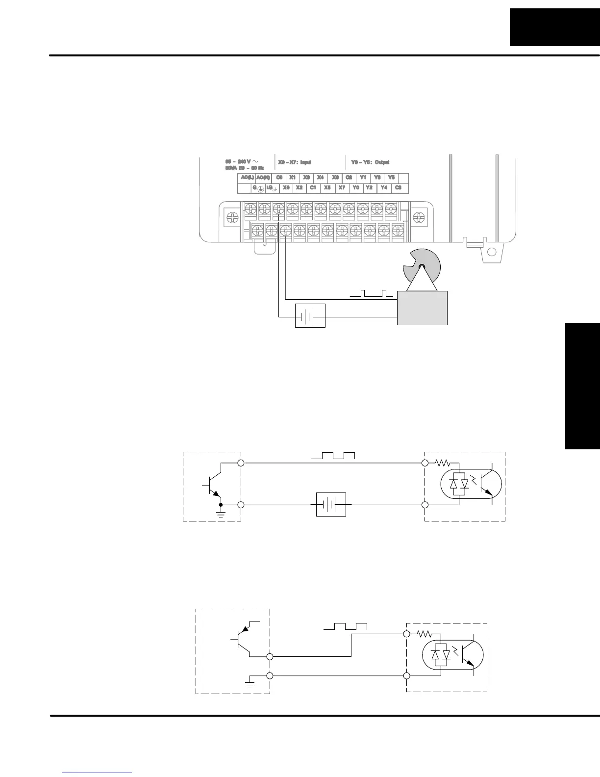
A general wiring diagram for counters/encoders to the DL05 in HSIO Mode 10 is
shown below. Many types of pulse-generating devices may be used, such as
proximity switches, single-channel encoders, magnetic or optical sensors, etc.
Devices with sinking outputs (NPN open collector) are probably the best choice for
interfacing. If the counter sources to the inputs, it must output 12 to 24 VDC. Note
that devices with 5V sourcing outputs will not work with DL05 inputs.
Counter Input Wiring
Signal Common
Signal
+–
12Ć24 VDC Supply
The DL05’s DC inputs are flexible in that they detect current flow in either direction,
so they can be wired to a counter with either sourcing or sinking outputs. In the
following circuit, a counter has open-collector NPN transistor outputs. It sinks
current from the PLC input point, which sources current. The power supply can be
the FA–24PS or another supply (+12VDC or +24VDC), as long as the input
specifications are met.
Counter Output
+–
X0 Input
Output
Ground
Input
Common
12Ć24 VDC Supply
(sinking)
(sourcing)
In the next circuit, an encoder has open-emitter PNP transistor outputs. It sources
current to the PLC input point, which sinks the current back to ground. Since the
encoder sources current, no additional power supply is required. However, note that
the encoder output must be 12 to 24 volts (5V encoder outputs will not work).
X0 Input
Output (sourcing)
Ground
Input
Common
+12 to 24VDC
(sinking)
Counter Output
Wiring Diagram
Interfacing to
Counter Outputs