Installation and
Safety Guidelines
Installation, Wiring,
and Specifications
2–51
Installation, Wiring, and Specifications
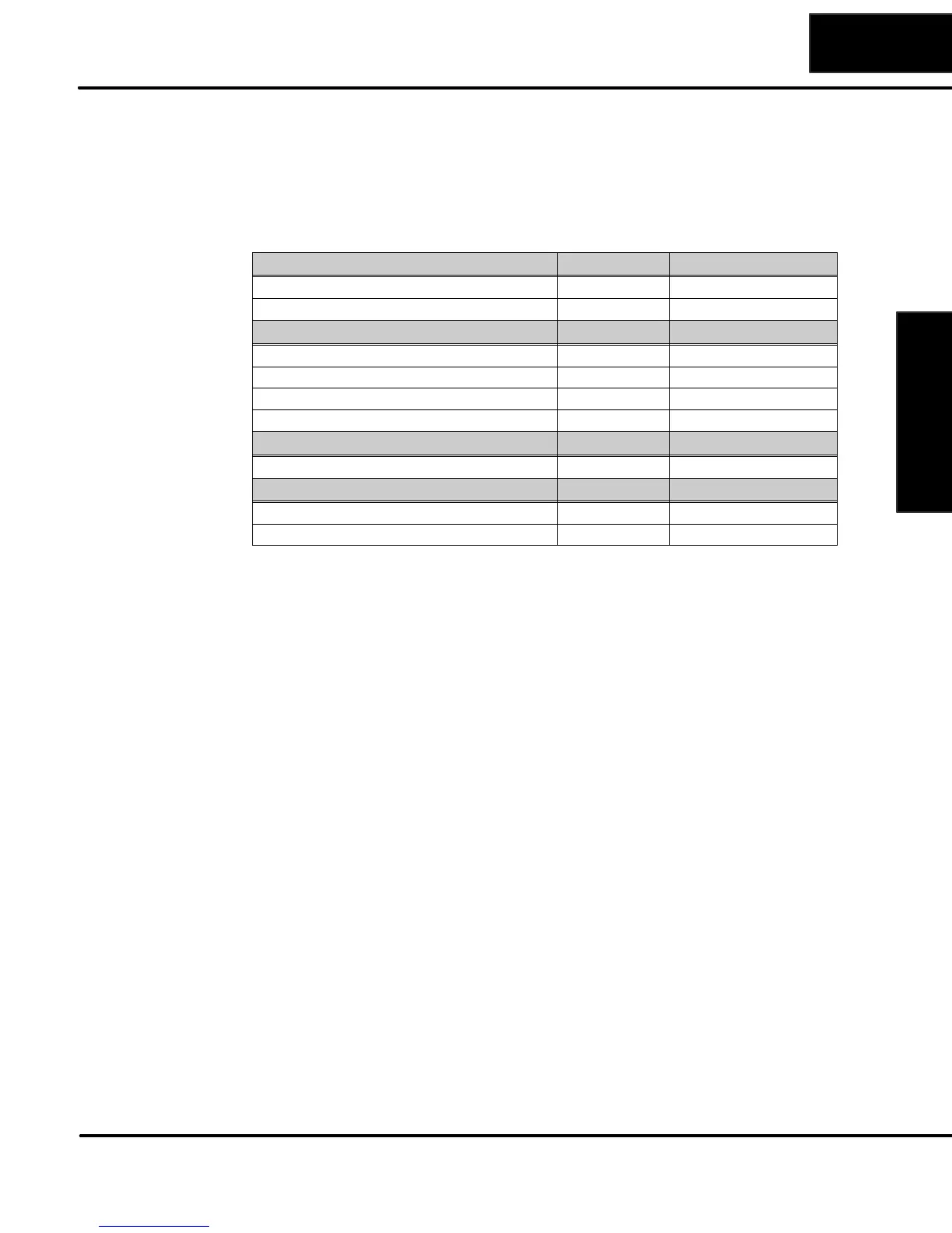
I/O Addressing
Each option module has a set number of I/O points. This holds true for both the
discrete modules and the analog modules. The following chart shows the number of
I/O points per module when used in the DL05 PLC.
DC Input Modules I/O Points Slot 1 I/O Address
D0–10ND3 10 Input X100 – X107 and X110 – X111
D0–16ND 16 Input X100 – X107 and X110 – X117
DC Output Modules I/O Points Slot 1 I/O Address
D0–10TD1 10 Output Y100 – Y107 and Y110 – Y111
D0–16TD1 16 Output Y100 – Y107 and Y110 – Y117
D0–10TD2 10 Output Y100 – Y107 and Y110 – Y111
D0–16TD2 16 Output Y100 – Y107 and Y110 – Y117
Relay Output Modules I/O Points Slot 1 I/O Address
D0–08TR 8 Output Y100 – X107
Combination Modules I/O Points Slot 1 I/O Address
D0–07CDR 4 Input, 3 Output X100 – X103 and Y100 – Y102
D0–08CDD1 4 Input, 4 Output X100 – X103 and Y100 – Y103
Module I/O Points
and Addressing