PID Loop Operation
Maintenance
and Troubleshooting
8–10
PID Loop Operation
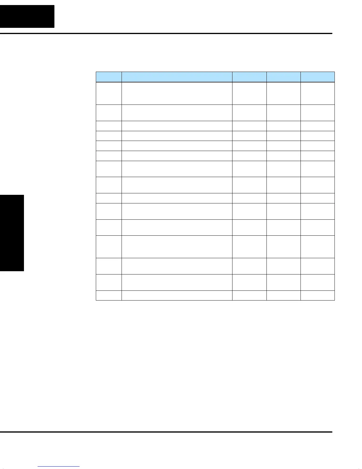
The individual bit definitions of the PID Mode Setting 2 word (Addr+01) are listed in
the following table. Additional information about the use of this word is available later
in this chapter.
Bit PID Mode Setting 2 Description Read/Write Bit=0 Bit=1
0 Input (PV) and Control Output Range
Unipolar/Bipolar select
(See Notes 1 and 2)
write unipolar bipolar
1 Input/Output Data Format select
(See Notes 1 and 2)
write 12 bit 15 bit
2 Analog Input filter write off on
3 SP Input limit enable write disable enable
4 Integral Gain (Reset) units select write seconds minutes
5 Select Autotune PID algorithm write closed loop open loop
6 Autotune selection write PID PI only
(rate = 0)
7 Autotune start read/write autotune
done
force start
8 PID Scan Clock (internal use) read – –
9 Input/Output Data Format 16-bit select
(See Notes 1 and 2)
write not
16 bit
select
16 bit
10 Select separate data format for input and
output (See Notes 2, and 3)
write same
format
separate
formats
11 Control Output Range
Unipolar/Bipolar select
(See Notes 2, and 3)
write unipolar bipolar
12 Output Data Format select
(See Notes 2, and 3)
write 12 bit 15 bit
13 Output data format 16-bit select
(See Notes 2, and 3)
write not
16 bit
select
16 bit
14–15 Reserved for future use – – –
Note 1: If the value in bit 9 is 0, then the values in bits 0 and 1 are read. If the value in
bit 9 is 1, then the values in bits 0 and 1 are not read, and bit 9 defines the
data format (the range is automatically unipolar).
Note 2: If the value in bit 10 is 0, then the values in bits 0, 1, and 9 define the input and
output ranges and data formats (the values in bits 11, 12, and 13 are not
read). If the value in bit 10 is 1, then the values in bits 0, 1, and 9 define only
the input range and data format, and bits 11, 12, and 13 are read and define
the output range and data format.
Note 3: If bit 10 has a value of 1 and bit 13 has a value of 0, then bits 11 and 12 are
read and define the output range and data format. If bit 10 and bit 13 each
have a value of 1, then bits 11 and 12 are not read, and bit 13 defines the data
format, (the output range is automatically unipolar).
PID Mode Setting 2
Bit Descriptions
(Addr + 01)