PID Loop Operation
Maintenance
and Troubleshooting
8–60
PID Loop Operation
Many applications do not require all 16 R/S steps. Use all zeros in the table for
unused steps. The R/S generator ends the profile when it finds ramp slope=0.
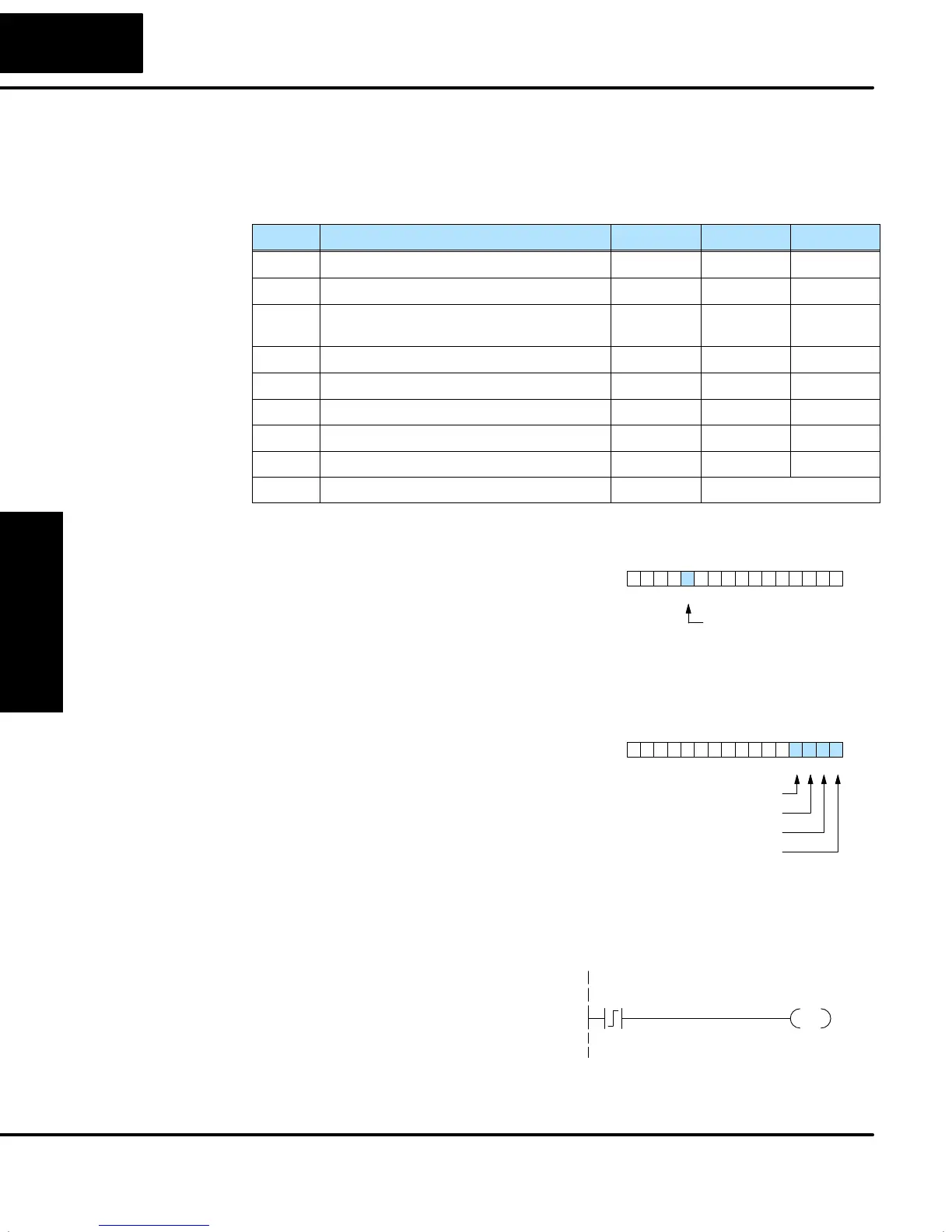
The individual bit definitions of the Ramp / Soak Table Flag (Addr+33) word is listed
in the following table.
Bit Ramp / Soak Flag Bit Description Read/Write Bit=0 Bit=1
0 Start Ramp / Soak Profile write –
0Õ1 Start
1 Hold Ramp / Soak Profile write –
0Õ1 Hold
2 Resume Ramp / soak Profile write –
0Õ1
Resume
3 Jog Ramp / Soak Profile write –
0Õ1 Jog
4 Ramp / Soak Profile Complete read – Complete
5 PV Input Ramp / Soak Deviation read Off On
6 Ramp / Soak Profile in Hold read Off On
7 Reserved read Off On
8–15 Current Step in R/S Profile read decode as byte (hex)
The main enable control to permit
ramp/soak generation of the SP value is
accomplished with bit 11 in the PID Mode 1
Setting V+00 word, as shown to the right.
The other ramp/soak controls in V+33
shown in the table above will not operate
unless this bit=1 during the entire
ramp/soak process.
PID Mode 1 Setting V+00
013456789101112131415 2Bit
Ramp/Soak
Generator Enable
The four main controls for the ramp/soak
generator are in bits 0 to 3 of the
ramp/soak settings word in the loop
parameter table. DirectSOFT32 controls
these bits directly from the ramp/soak
settings dialog. However, you must use
ladder logic to control these bits during
program execution. We recommend using
the bit-of-word instructions.
Ramp/Soak Settings V+33
013456789101112131415 2Bit
Jog
Resume
Hold
Start
Ladder logic must set a control bit to a “1” to command the corresponding function.
When the loop controller reads the ramp/soak value, it automatically turns off the bit
for you. Therefore, a reset of the bit is not required, when the CPU is in Run Mode.
The example program rung to the right
shows how an external switch X0 can turn
on, and the PD contact uses the leading
edge to set the proper control bit to start
the ramp soak profile. This uses the Set
Bit-of-word instruction.
X0
SET
B2033.0
Start R/S Generator
Ramp/Soak
Table Flags
Ramp/Soak
Generator Enable
Ramp/Soak
Controls