Installation, Wiring,
and Specifications
2–10
Installation, Wiring, and Specifications
Wiring Guidelines
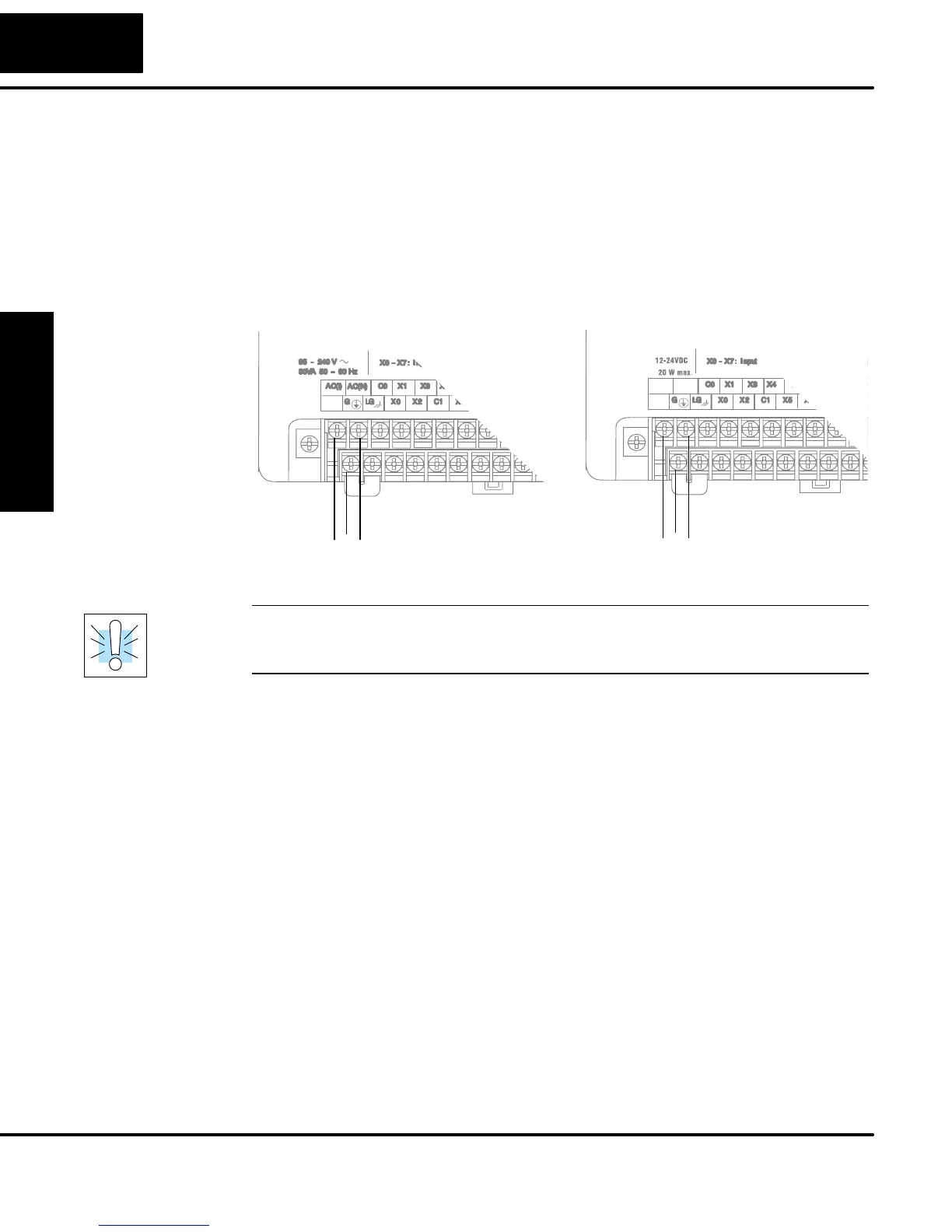
Connect the power input wiring for the DL05. Observe all precautions stated earlier
i
n this manual. For more details on wiring, see Chapter 2 on Installation, Wiring, an
pecifications. When the wiring is complete, close the connector covers. Do no
pply power at this time.
110/220 VAC Power Input
95 – 240 VAC
LNG
12/24 VDC Power Input
+
–
12 – 24 VDC
+–G
WARNING: Once the power wiring is connected, secure the terminal block cover in
the closed position. When the cover is open there is a risk of electrical shock if you
accidentally touch the connection terminals or power wiring.
There are no internal fuses for the input power circuits, so external circuit protection
is needed to ensure the safety of service personnel and the safe operation of the
equipment itself. To meet UL/CUL specifications, the input power must be fused.
Depending on the type of input power being used, follow these fuse protection
recommendations:
208/240 VAC Operation
When operating the unit from 208/240 VAC, whether the voltage source is a
step-down transformer or from two phases, fuse both the line (L) and neutral (N)
leads. The recommended fuse size is 0.375A.
110/125 VAC Operation
When operating the unit from 110/125 VAC, it is only necessary to fuse the line (L)
lead; it is not necessary to fuse the neutral (N) lead. The recommended fuse size is
0.5A.
for Input Power