PID Loop Operation
Maintenance
8–45
PID Loop Operation
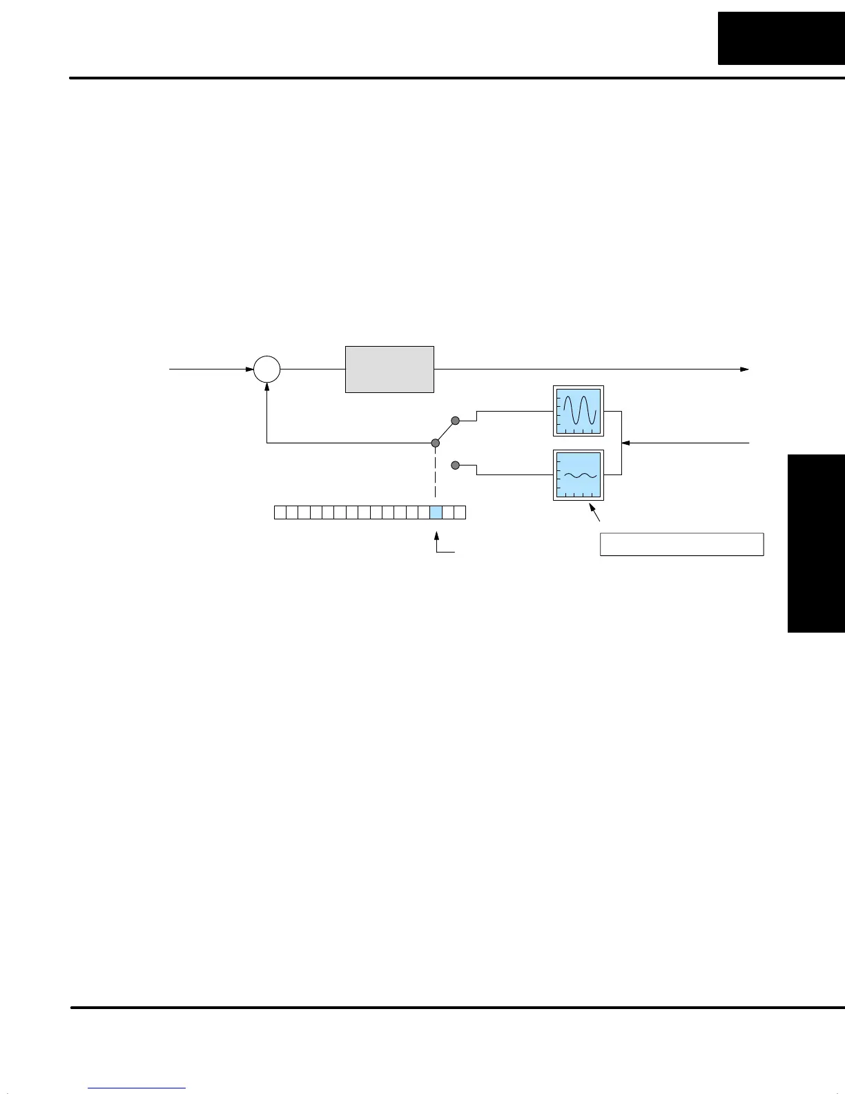
PV Analog Filter
A noisy PV signal can make tuning difficult and can cause the control output to be
more extreme than necessary, as the output tries to respond to the peaks and
valleys of the PV. There are two equivalent methods of filtering the PV input to make
the loop more stable. The first method is accomplished using the DL05’s built-in
filter. The second method achieves a similar result using ladder logic.
The DL05 provides a selectable first-order low-pass PV input filter which can be
particularly helpful during auto tuning, using the closed-loop method. Shown in the
figure below, we strongly recommend the use of a filter during auto tuning. Yo u
may disable the filter after auto tuning is complete, or continue to use it if the PV input
signal is noisy.
Loop
Calculation
S
+
–
Control Output
PID Mode 2 Setting V+01
013456789101112131415 2Bit
PV filter
enable/disable
0
1
Unfiltered
PV
Filtered
PV
Setpoint
Process Variable
Loop Table
V+24 FIlter constantXXXX
Bit 2 of PID Mode Setting 2 provides the enable/disable control for the low-pass PV
filter (0=disable, 1=enable). The roll-off frequency of the single-pole low-pass filter is
controlled by using register V+24 in the loop parameter table, the filter constant. The
data format of the filter constant value is BCD, with an implied decimal point 00X.X,
as follows:
S The filter constant has a valid range of 000.1 to 001.0.
S DirectSOFT32 converts values above the valid range to 001.0 and
values below this range to 000.1
S Values close to 001.0 result in higher roll-off frequencies, while values
closer to 000.1 result in lower roll-off frequencies.
We highly recommend using DirectSOFT32 for the auto tuning interface. The
duration of each auto tuning cycle will depend on the mass of your process. A
slowly-changing PV will result in a longer auto tune cycle time.
When the auto tuning is complete, the proportional, integral, and derivative gain
values are automatically updated in loop table locations V+10, V+11, and V+12
respectively. The sample time in V+07 is also updated automatically. You can test
the validity of the values the auto tuning procedure yields by measuring the
closed-loop response of the PV to a step change in the output. The instructions on
how to do this are in the section on the manual tuning procedure.
The DL05 Built-in
Analog Filter