PID Loop Operation
Maintenance
8–25
PID Loop Operation
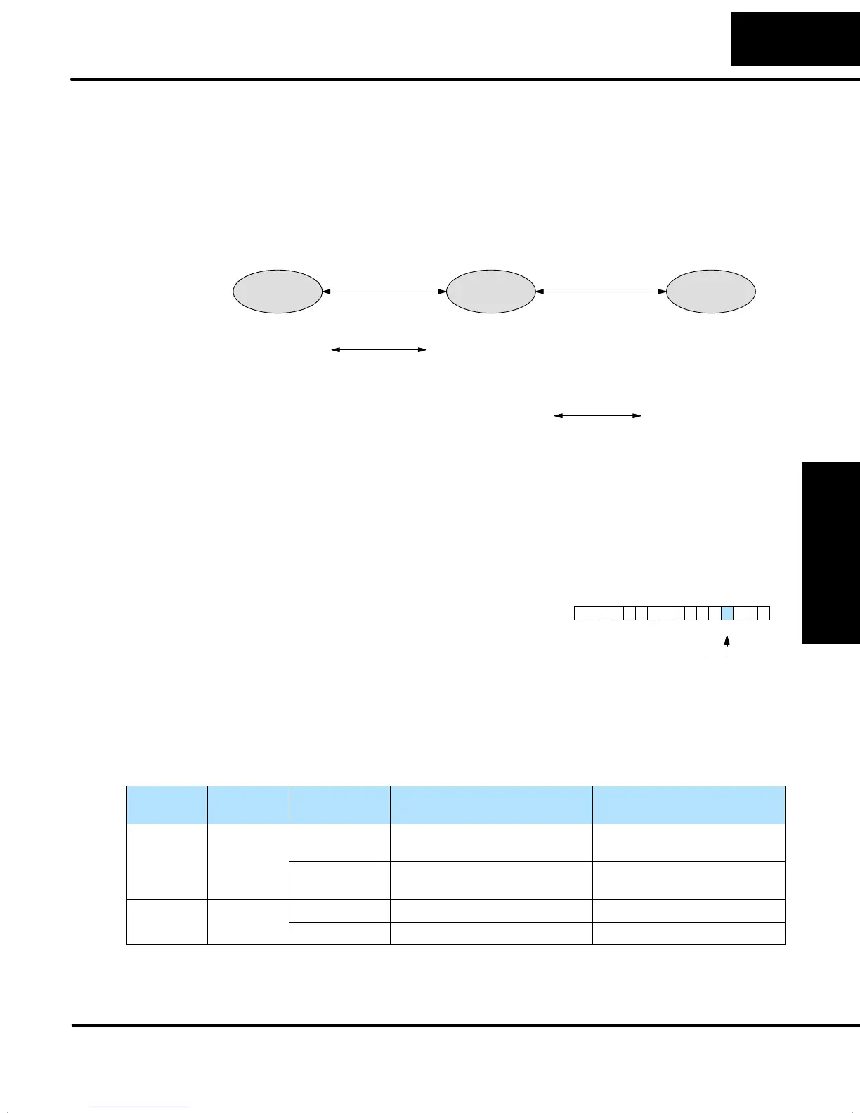
In process control, the word “transfer” has a particular meaning. A loop transfer
occurs when we change its mode of operation, as shown below. When we change
loop modes, what we are really doing is causing a transfer of control of some loop
parameter from one source to another. For example, when a loop changes from
Manual Mode to Automatic Mode, control of the output changes from the operator to
the loop controller. When a loop changes from Automatic Mode to Cascade Mode,
control of the SP changes from its original source in Auto Mode to the output of
another loop (the major loop).
Manual Automatic Cascade
Mode change
Transfer
Operator
generates
loop output
PID
calculates
loop output
SP
generated
local to loop
SP
generated
remotely by
major loop
Transfer
Mode change
The basic problem of loop transfers is the two different sources of the loop parameter
being transferred will have different numerical values. This causes the PID
calculation to generate an undesirable step change, or “bump” on the control output,
thereby upsetting the loop to some degree. The “bumpless transfer” feature
arbitrarily forces one parameter equal to another at the moment of loop mode
change, so the transfer is smooth (no bump on the control output).
The bumpless transfer feature of the DL05
loop controller is available in two types:
Bumpless I, and Bumpless II. Use
DirectSOFT32’s PID Setup dialog box to
select transfer type. Or, you can use bit 3
of PID Mode 1 V+00 setting as shown.
PID Mode 1 Setting V+00
013456789101112131415 2Bit
Bumpless Transfer I / II select
The characteristics of Bumpless I and II transfer types are listed in the chart below.
Note that their operation also depends on which PID algorithm you are using, the
position or velocity form of the PID equation. Note that you must use Bumpless
Transfer type I when using the velocity form of the PID algorithm.
Transfer
Type
Transfer
Select Bit
PID Algorithm Manual-to-Auto
Transfer Action
Auto-to-Cascade
Transfer Action
Bumpless
Transfer I
0 Position Forces Bias = Control Output
Forces SP = PV
Forces Major Loop Output =
Minor Loop PV
Velocity Forces SP = PV Forces Major Loop Output =
Minor Loop PV
Bumpless
1 Position Forces Bias = Control Output none
Transfer II
Velocity none none
Bumpless
Transfers