Drum Instruction
Programming
6–15
Drum Instruction Programming
Drum instructions use four counters in the CPU. The ladder program can read the
counter values for the drum’s status. The ladder program may write a new preset
step number to CT(n+2) at any time. However, the other counters are for monitoring
purposes only.
Counter Number Ranges of (n) Function Counter Bit Function
CT(n) 0 – 174 Counts in step CTn = Drum Complete
C( n+1) 1 – 175 Timer value CT(n+1) = (not used)
CT( n+2) 2 –176 Preset Step CT(n+2) = (not used)
CT( n+3) 3 –177 Current Step CT(n+3) = (not used)
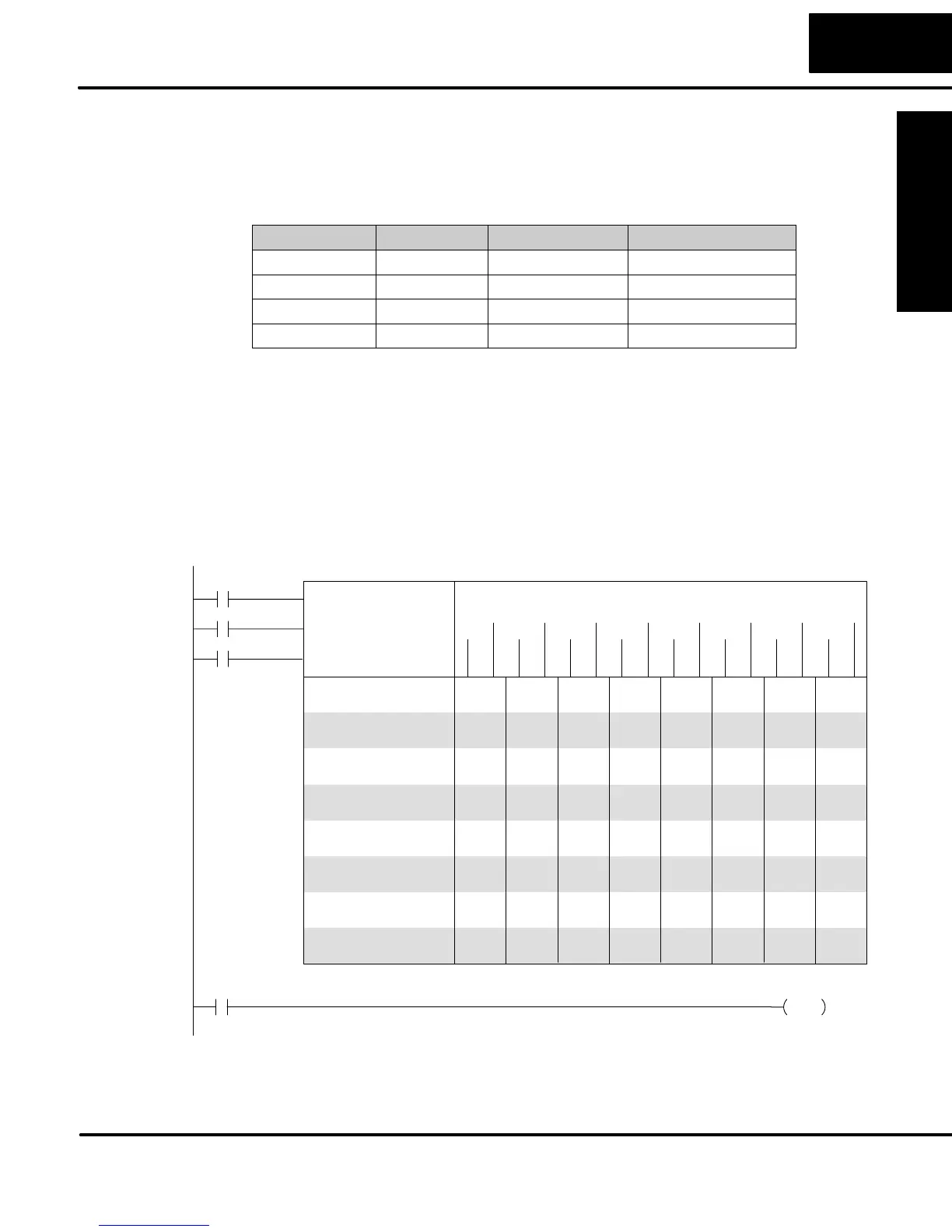
The following ladder program shows the EDRUM instruction in a typical ladder
program, as shown by DirectSOFT. Steps 1 through 11 are used, and all sixteen
output points are used. The preset step is step 1. The timebase runs at (K10 x 0.01) =
0.1 second per count. Therefore, the duration of step 1 is (1 x 0.1) = 0.1 second. Note
that step 1 is time-based only (event is left blank). And, the output pattern for step 1
programs all outputs off, which is a typically desirable powerup condition. In the last
rung, the Drum Complete bit (CT4) turns on output Y0 upon completion of the last
step (step 11). A drum reset also resets CT4.
1 K0001
EDRUM CT 4
Step Preset K 1
0.01 sec/Count: K 10
2 K0020
3 K0150
4 K0048
5 K0180
6 K0923
7 K0120
8 K0864
9 K1200
10 K0400
11 K0000
12
13
14
15
16
ffffffffffffffff
FffFFffffffFffFf
ffFfFfffFffFfFff
fFfffFfffFFFfFFf
fFfffFffFffffFFf
FffFffFffFfFFffF
fFfFfffFfFFfFffF
FffFffFFfFffffFF
ffffffFFFfffFfFf
fFfFFffffFFffFff
FffffFfffFfffFFF
ffffffffffffffff
ffffffffffffffff
ffffffffffffffff
ffffffffffffffff
ffffffffffffffff
(Y3) (Y7) (C30) (Y2) (C2) (Y6) (Y4) (C10)
(C34) (Y6) (C14) (Y0) (C4) (Y5) (Y1) (C7)
Step # Counts Event
Y4
X1
X2
C0
C1
X0
X5
X3
Y7
C20
Start
Jog
DirectSOFT Display
X0
X1
Drum Complete
CT4
Y0
OUT
Reset
X2
15 0