The synchronization of several drives needs high refresh rates to assure optimum
results. Set the corresponding time (i.e. TxPDO1 Time 931
) at the transmit side to
a low value. For the usage of the sync-function at the system bus set SYNC-Time
919 to a low value.
The bus load of the system bus must have sufficient reserves for proper operation.
The system bus is described in the manuals of the extension modules with system
bus interface.
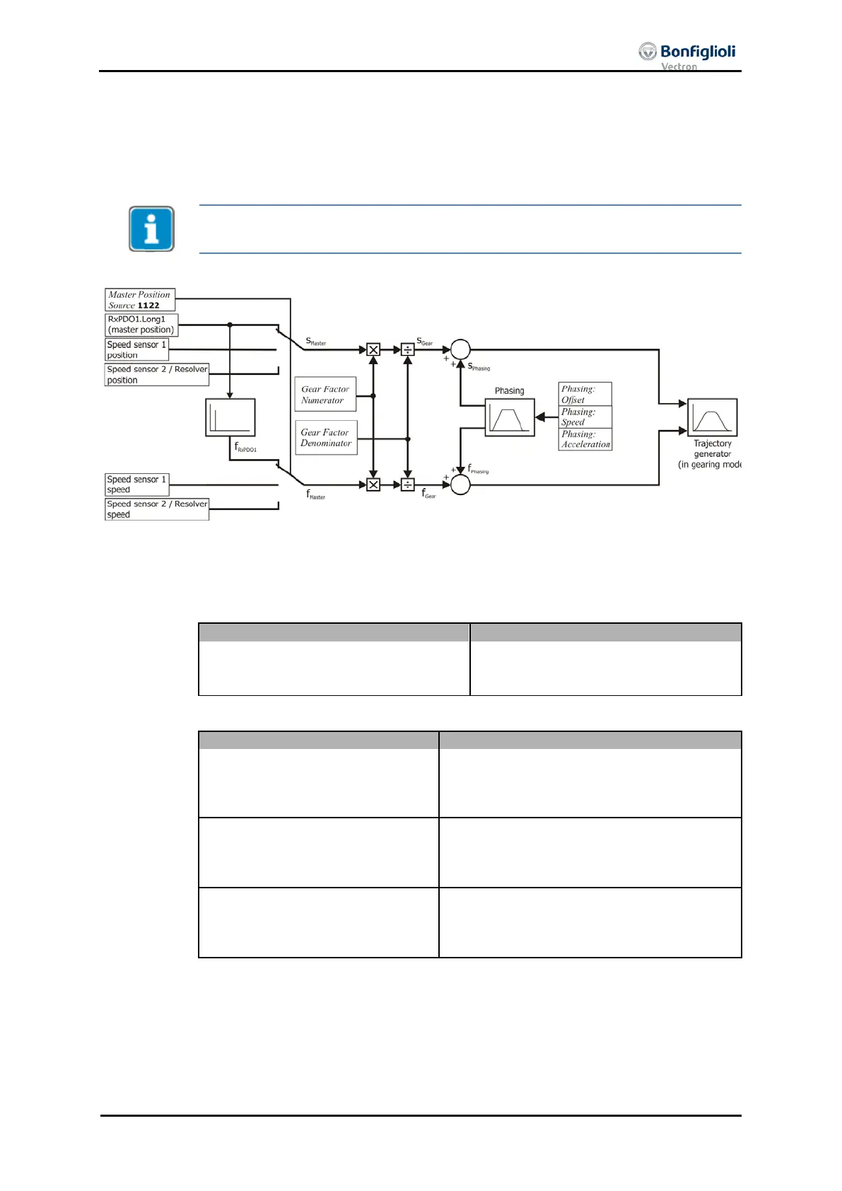
Block diagram: electronic gear and phasing function
The master position and speed is multiplied with the
gear factor
. When a
Phasing
is
started, the Phasing profile is added to the Master Speed until the Phasing offset is
reached.
The
gear factor
is defined by the following Objects or parameters:
Gear factor Resync on change
Resync. on Change of Gear-Factor
The
Phasing
is defined by the following Objects or parameters:
0x5F12/1
0x5F13/1
Phasing 1: Offset
Phasing 2: Offset
1125.2
1125.3
0x5F12/2
0x5F13/2
Phasing 2: Speed
Phasing 3: Speed
1126.2
1126.3
0x5F12/3
0x5F13/3
Phasing 2: Acceleration
Phasing 3: Acceleration
1127.2
1127.3
04/13 CM-CAN ACU 219

 Loading...


