Start Electronic Gear and Status bits
Gearing operation is started by Control word bit 4 “Start Gearing”. The drive acceler-
ates according to 0x6083
Profile acceleration
. As soon as the slave speed is coupled to
the master speed, Status word bit 10 “Target reached / Gear coupled
coupling conditions are set with objects 0x5F15
In gear threshold
and 0x5F16
The coupled slave axis is controlled by the master. While the Slave is coupled speed,
acceleration and deceleration is defined by the master. While coupled the Objects
0x6083 and 0x6084 have no effect.
Setting
Halt
to 1 interrupts an actual processed movement. The axle is stopped with
the ramp 0x6084.
The “target reached” bit is reset at the start of the deceleration and
set again after reaching zero speed. The drive remains in state
Resetting
Halt
to 0 restarts processing of the interrupted movement
reached” bit is rese
t at the start of the acceleration and set again when meeting the
“In gear” criteria set in objects 0x5F15
In gear threshold
and 0x5F16
In gear time
..
With the phasing function, the slave position is offset from the received position of the
master by the Phasing-Position.
The Phasing is described in chapter 12.4.19 “0x5F11/n…0x5F14/n Phasing 1…4”.
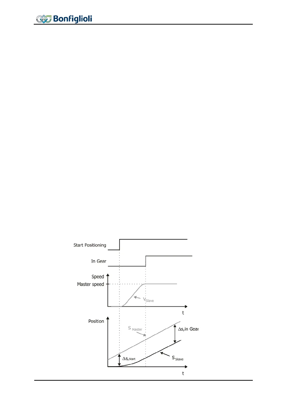
Function without Direct Synchronization
(“Standard Synchronization”)
The drive accelerates the master speed at the ramps parameterized in the motion
block. As soon as the master speed is reached for the first time, the drive is synchr
o-
nized with the master drive. The slave is engaged at the current position and operates
at a synchronous angle with the master. In the case of a relative positioning oper
tion, this engaging position is used as the start position.
The
relative position shift between master and slave due to the acceleration
is not compensated.
220 CM-CAN ACU 04/13

 Loading...


