Introduction
ClareVision Plus Network Video Recorder User Manual 7
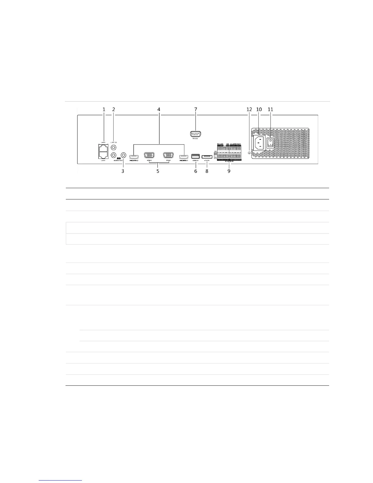
Rear panel
Figure 5: 64-Channel NVR rear panel
(Model: CVP-P64050-10)
Table 5: 64-Channel NVR rear panel connections
RCA connector for the audio input.
2 RCA connectors for audio output.
HDMI video output connector.
DB9 connector for VGA output. Display local video output
and menu.
Connects USB devices – for example, a USB mouse or writer.
Connector for RS-232 devices.
Connects external SATA HDD, CD/DVD-RM.
2 eSATA interfaces.
D Plus/D- pin connects to Ta, Tb pin of controller. For
cascading devices, the first NVR’s D Plus/D- pin connects
with the D Plus/D- pin of the next NVR.
Connector for alarm input.
Connector for alarm output.
AC 100 to 240 V power supply.
Switch for turning on/off the device.
Ground (connect before starting the NVR).