Introduction
8 ClareVision Plus Network Video Recorder User Manual
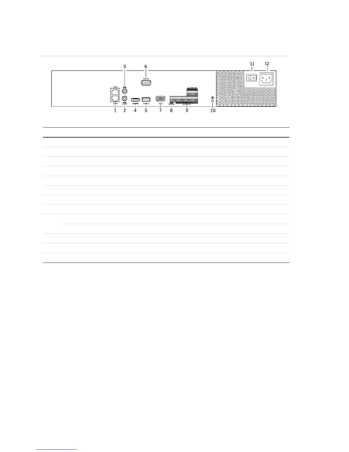
Figure 6: 16-Channel and 32-Channel rear panel connections
(Models: CVP-M321650-08 and CVP-M161650-04)
Table 6: 16-Channel and 32 Channel rear panel connections
RCA connector for audio output.
RCA connector for audio input.
Connects USB devices – for example, a USB mouse or writer.
Connector for the RS-232 devices
DB9 connector for VGA output.
Half-duplex connector for RS-485 devices.
Connector for alarm input
Connector for alarm output.
Ground (must be connected when the NVR starts.)
AC 100 V to 240 V power input.
Switch for turning the device on/off.