Chapter 7
| Spanning Tree Algorithm
Overview
– 181 –
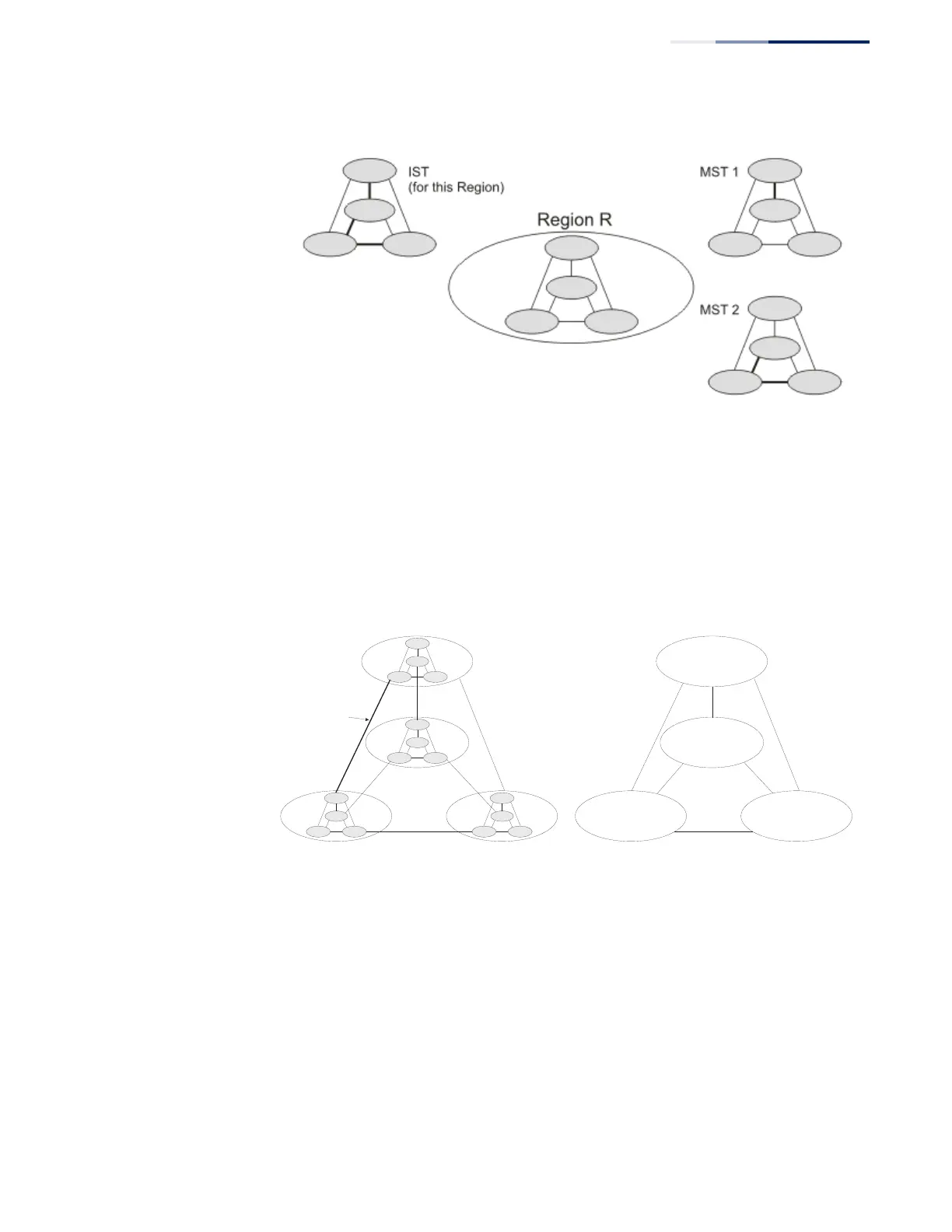
Figure 104: MSTP Region, Internal Spanning Tree, Multiple Spanning Tree
An MST Region consists of a group of interconnected bridges that have the same
MST Configuration Identifiers (including the Region Name, Revision Level and
Configuration Digest – see “Configuring Multiple Spanning Trees” on page 196). An
MST Region may contain multiple MSTP Instances. An Internal Spanning Tree (IST)
is used to connect all the MSTP switches within an MST region. A Common
Spanning Tree (CST) interconnects all adjacent MST Regions, and acts as a virtual
bridge node for communications with STP or RSTP nodes in the global network.
Figure 105: Common Internal Spanning Tree, Common Spanning Tree, Internal
Spanning Tree
MSTP connects all bridges and LAN segments with a single Common and Internal
Spanning Tree (CIST). The CIST is formed as a result of the running spanning tree
algorithm between switches that support the STP, RSTP, MSTP protocols.
Once you specify the VLANs to include in a Multiple Spanning Tree Instance (MSTI),
the protocol will automatically build an MSTI tree to maintain connectivity among
each of the VLANs. MSTP maintains contact with the global network because each
instance is treated as an RSTP node in the Common Spanning Tree (CST).
Region 1
Region 4
Region 2 Region 3
CIST
IST
Region 1
Region 4
Region 2 Region 3
CST

 Loading...