Chapter 10
| Quality of Service
Configuring a Class Map
– 231 –
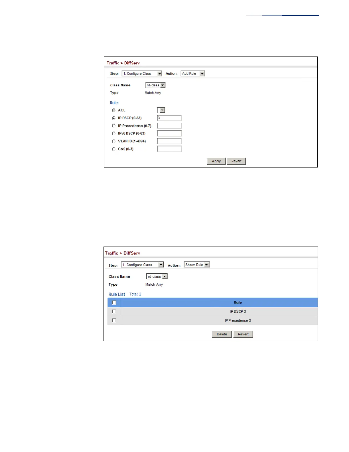
Figure 141: Adding Rules to a Class Map
To show the rules for a class map:
1. Click Traffic, DiffServ.
2. Select Configure Class from the Step list.
3. Select Show Rule from the Action list.
Figure 142: Showing the Rules for a Class Map
 Loading...