Chapter 7
| Spanning Tree Algorithm
Configuring Multiple Spanning Trees
– 196 –
Web Interface
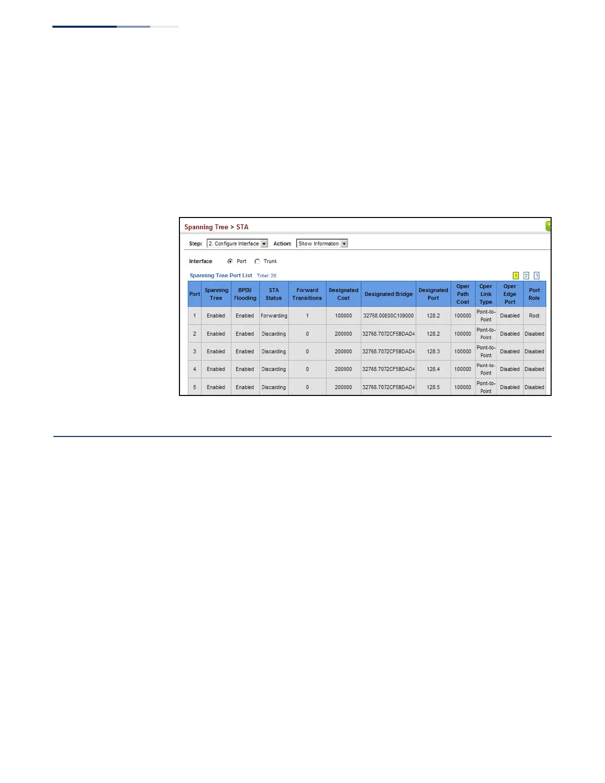
To display interface settings for STA:
1. Click Spanning Tree, STA.
2. Select Configure Interface from the Step list.
3. Select Show Information from the Action list.
Figure 113: Displaying Interface Settings for STA
Configuring Multiple Spanning Trees
Use the Spanning Tree > MSTP (Configure Global) page to create an MSTP instance,
or to add VLAN groups to an MSTP instance.
Command Usage
MSTP generates a unique spanning tree for each instance. This provides multiple
pathways across the network, thereby balancing the traffic load, preventing wide-
scale disruption when a bridge node in a single instance fails, and allowing for
faster convergence of a new topology for the failed instance.
By default all VLANs are assigned to the Internal Spanning Tree (MST Instance 0)
that connects all bridges and LANs within the MST region. This switch supports up
to 32 instances. You should try to group VLANs which cover the same general area
of your network. However, remember that you must configure all bridges within
the same MSTI Region (page 183) with the same set of instances, and the same
instance (on each bridge) with the same set of VLANs. Also, note that RSTP treats
each MSTI region as a single node, connecting all regions to the Common Spanning
Tree.

 Loading...