Configuring PoE
7-4 Configuring System Power and PoE
• Class mode, in which the PoE controller manages power based on the IEEE 802.3af/.3at
definition of the class limits advertised by the attached devices, with the exception that for
class 0 and class 4 devices, actual power consumption will always be used. In this mode, the
maximum amount of power required by a device in the advertised class is reserved for the
port, regardless of the actual amount of power being used by the device.
Power management to PDs is configured with the command set inlinepower management. PoE
classes are defined in Table 7-1 on page 7-2.
Configuring PoE
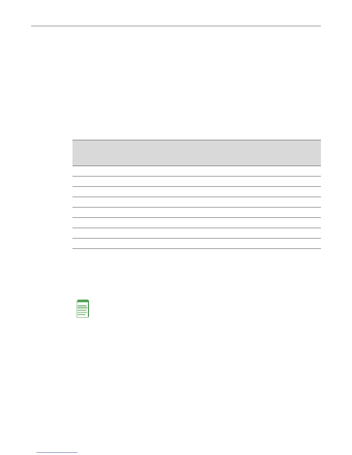
Table 7-2 lists the PoE settings that you can configure through the CLI on each PoE-compliant
Enterasys device.
Refer to the appropriate device-specific PoE configuration procedure.
• Stackable fixed switches A4, B3, and C3: Procedure 7-1 on page 7-5
• Stackable fixed switches B5 and C5: Procedure 7-2 on page 7-6
• Standalone G-Series: Procedure 7-3 on page 7-7
Table 7-2 PoE Settings Supported on Enterasys Devices
Setting
A4
B3
B5
C3
C5
G-Series
Port-specific PoE parameters XXXXXX
SNMP traps XXXXXX
PoE usage threshold XXXXXX
PD detection method XXXXXX
System power redundancy X X
System power allocation X
Module power allocation X
PD power management X X X
Note: You must be logged on to the Enterasys device with read-write access rights to use the
commands shown in the procedures in the following sections.

 Loading...


