Link Aggregation Overview
11-6 Configuring Link Aggregation
Because port 6 has both a different speed and a higher priority than the port with the lowest
priority in the LAG, it is not moved to the attached state.
If LAG members with different port speeds should tie for the lowest port priority, the LAG
member with the lowest port number breaks the tie. In our example, should all three ports have
the same port priority, ports 4 and 5 would still be the ports moved to the attached state because
port 4 has the lowest port number and port 5 has the same port speed as port 4.
If in our example you wanted the reverse outcome of port 6 moved to the attached state instead of
ports 4 and 5, setting port 6 to a lower priority than ports 4 and 5, as well as enabling the single
port LAG feature on this device, would accomplish that goal.
Aggregatable ports not moved to the attached state are made available to form another LAG
providing a LAG resource is available for this system. Port 6 in Figure 11-1 on page 11-4, was not
moved to the attached state. The only criteria port 6 does not meet to form its own LAG is rule 4:
being a single aggregatable port. The single port LAG feature must be enabled for port 6 to form a
LAG. If single port LAG is enabled on this system, port 6 would form and attach to LAG 3.
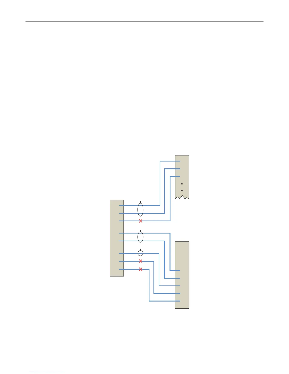
Figure 11-2 illustrates the three LAGs described in this example.
Figure 11-2 LAGs Moved to Attached State
Should an aggregatable port be available with all LAG resources depleted for this system, the port
is placed in LACP standby state. Ports in standby state do not forward traffic. If all ports initially
moved to the attach state for a given LAG become unavailable, a LAG resource will then be
available. LACP will initiate a new selection process using the ports in standby state, using the
same rules as the initial process of forming LAGs and moving ports to the attached state.
PARTNER
Port
Speed
Device
B
Device
A
Device
C
LAG 1
LAG 2
LAG 3
Admin
Key
ACTOR
Port
Speed
Admin
Key
100
100
100
100
100
100
100
100
100
100
100
100M
100M
100M
100M
100M
1Gb
1Gb
1Gb
100
100
200
100
100
100
300
400
100M
100M
100M
100M
100M
1Gb
1Gb
1Gb
100M
100M
100M
1
2
3
4
5
6
7
8
1
2
3
4
5
6
7
8
1
2
3

 Loading...


