Configuring MSTP
Fixed Switch Configuration Guide 15-27
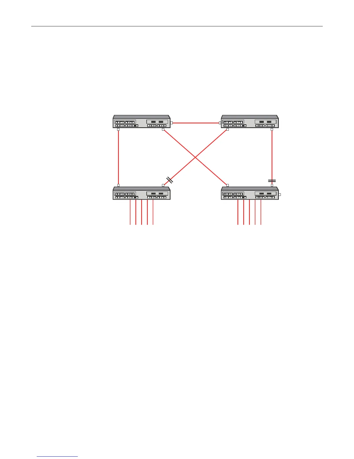
Example 2: Configuring MSTP for Maximum Bandwidth Utilization
This example illustrates the use of MSTP for maximum bandwidth utilization. Maximum
bandwidth utilization takes place when all bridges participate on all VLANs. Figure 15-13 shows
that with a single Spanning Tree configuration, only a single link towards the root forwards on a
bridge. The alternate ports are blocking.
Figure 15-13 Maximum Bandwidth Utilization in a Single STP Network Configuration
In Figure 15-13, Bridge A is the root of the Spanning Tree because it has the lowest priority. Bridge
D port ge.1.2 forwards traffic to Bridge A. Bridge D port ge.1.1 is blocking. Bridge C port ge.1.1
forwards traffic to Bridge A. Bridge C port ge.1.2 is blocking. This single Spanning Tree
configuration prevents maximum bandwidth utilization for this network.
Figure 15-14 on page 15-28 shows that with an MSTP configuration each link can be forwarding
for some VLAN and each VLAN has a path to the root bridge.
ge.1.1
ge.1.2 ge.1.2
ge.1.3 ge.1.3
ge.1.1
ge.1.2
ge.1.1
ge.1.2
ge.1.1
Bridge A
priority = 4096
Bridge B
priority = 8192
Bridge C
priority = 32768
Bridge D
priority = 32768

 Loading...


