Configuring OSPF Areas
22-12 Configuring OSPFv2
Example
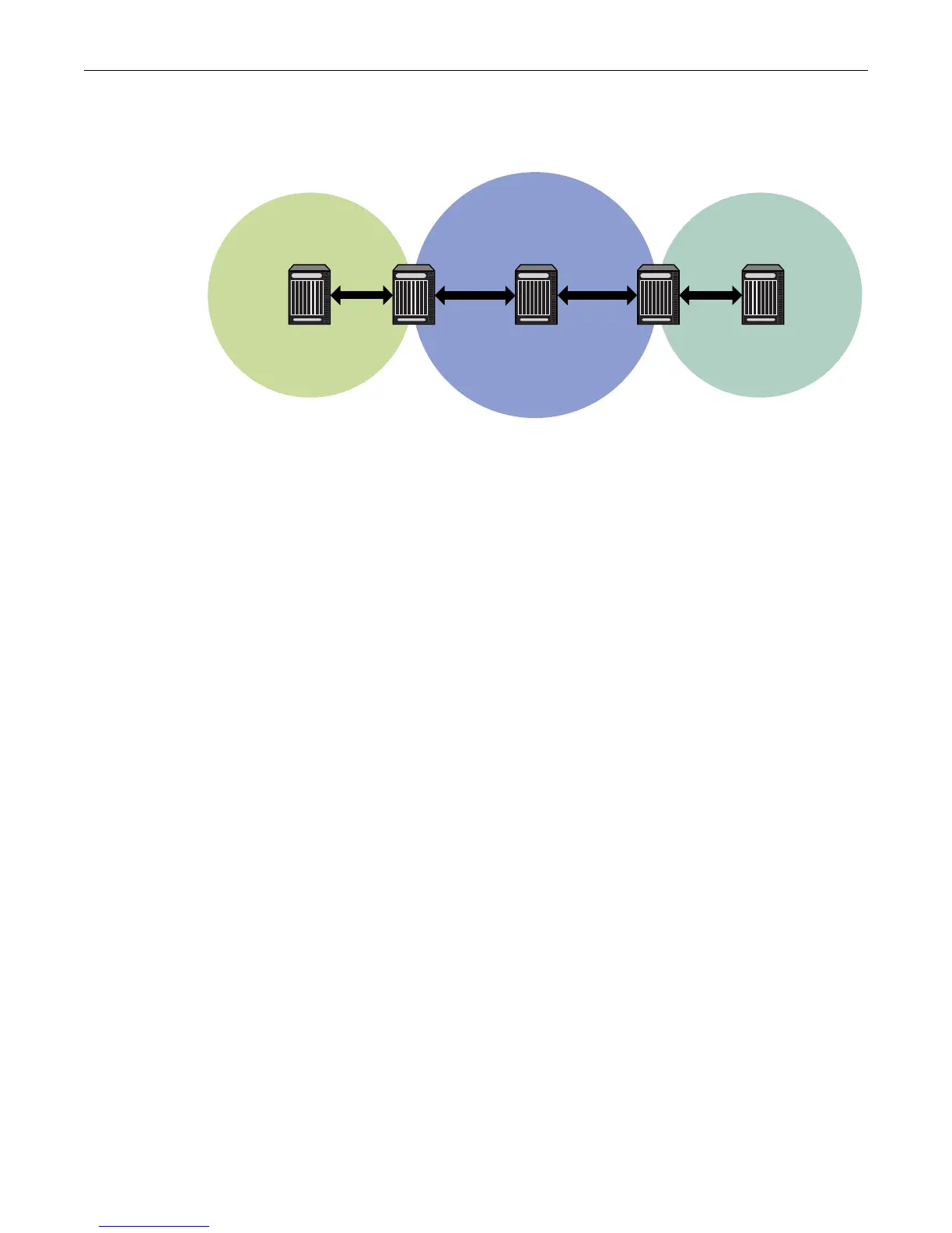
Figure 22-5 OSPF NSSA Topology
Using the topology shown in Figure 22-5, the following code examples will configure Router 2 as
the ABR between Area 1 and the backbone area 0. Router 4 is configured as an ASBR connected to
a RIP autonomous system. Router 2 will translate Type 7 LSAs from the connected domain to Type
5 routes into the backbone.
Router 4 will be configured to redistribute connected and RIP routes.
Router 2 (ABR)
Router 2(su)->router(Config)#router id 2.2.2.2
Router 2(su)->router(Config)#router ospf 1
Router 2(su)->router(Config-router)#area 0.0.0.1 nssa default-information-
originate
Router 3 (IR)
Router 3(su)->router(Config)#router id 3.3.3.3
Router 3(su)->router(Config)#router ospf 1
Router 3(su)->router(Config-router)#area 0.0.0.1 nssa
Router 4(ASBR)
Router 4(su)->router(Config)#router id 4.4.4.4
Router 4(su)->router(Config)#router ospf 1
Router 4(su)->router(Config-router)#redistribute connected
Router 4(su)->router(Config-router)#redistribute rip
Configuring Area Virtual-Links
The backbone area 0 cannot be disconnected from any other areas in the AS. Disconnected areas
will become unreachable. To establish and maintain backbone connectivity, virtual-links can be
configured through non-backbone areas for the purpose of connecting a disconnected area with
the backbone through a backbone connected area. The two endpoints of a virtual link are ABRs,
both of which belong to the backbone connected area (also referred to as the transit area); one of
which belongs to the area disconnected from the backbone. Virtual links cannot be configured
through stub areas.
Area 1
Backbone
Router 2
RIP
Router 3 Router 4 Router 5Router 1

 Loading...


