Basic OSPF Topology Configuration
22-4 Configuring OSPFv2
1. See “Configuring OSPF Areas” on page 22-8 for additional discussion of OSPF area
configuration. This basic configuration requires the configuration of four interfaces and associated
IP addresses. Also configured are two loopback interfaces, to use for the router IDs.
Configuring the Router ID
OSPF initially assigns all routers a router ID based on the highest loopback IP address of the
interfaces configured for IP routing. If there is no loopback interface configured then it will be the
highest VLAN IP address configured. This unique value, which is included in the hello packet
transmitted in Link State Advertisements (LSA), identifies one router to another and helps
establish adjacencies among OSPF routers. When you specify an interface as the router ID, this
value supersedes the default ID.
Example
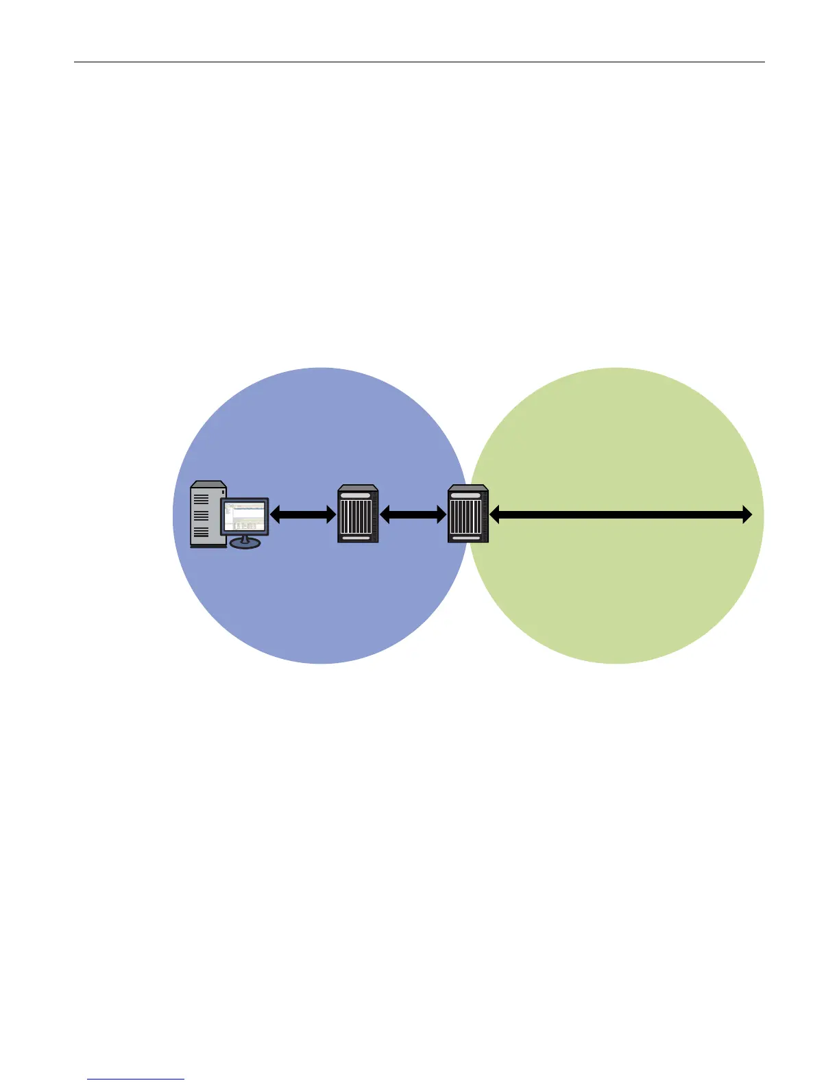
Figure 22-1 Basic OSPF Topology
The following code example configures the basic OSPF topology as displayed in Figure 22-1
above.
Router 1 CLI Input
Router 1(su)->router(Config)#interface vlan 1
Router 1(su)->router(Config-if(Vlan 1))#ip address 172.10.1.1 255.255.255.0
Router 1(su)->router(Config-if(Vlan 1))#ip ospf areaid 0.0.0.1
Router 1(su)->router(Config-if(Vlan 1))#ip ospf enable
Router 1(su)->router(Config-if(Vlan 1))#no shutdown
Router 1(su)->router(Config-if(Vlan 1))#exit
Router 1(su)->router(Config)#interface vlan 2
Router 1(su)->router(Config-if(Vlan 2))#ip address 172.10.2.1 255.255.255.0
Router 1(su)->router(Config-if(Vlan 2))#ip ospf areaid 0.0.0.1
Router 1(su)->router(Config-if(Vlan 2))#ip ospf enable
Backbone
Area 0
Area 1
Router 2Router 1
Host 1
172.10.1.99/24
172.10.1.1/2 4
Vlan 1 Vlan 2
Vlan 2
172.10.2.2/24
Vlan 3
172.2.1.1/24
172.10.2.1/24

 Loading...


