Link Aggregation Overview
11-4 Configuring Link Aggregation
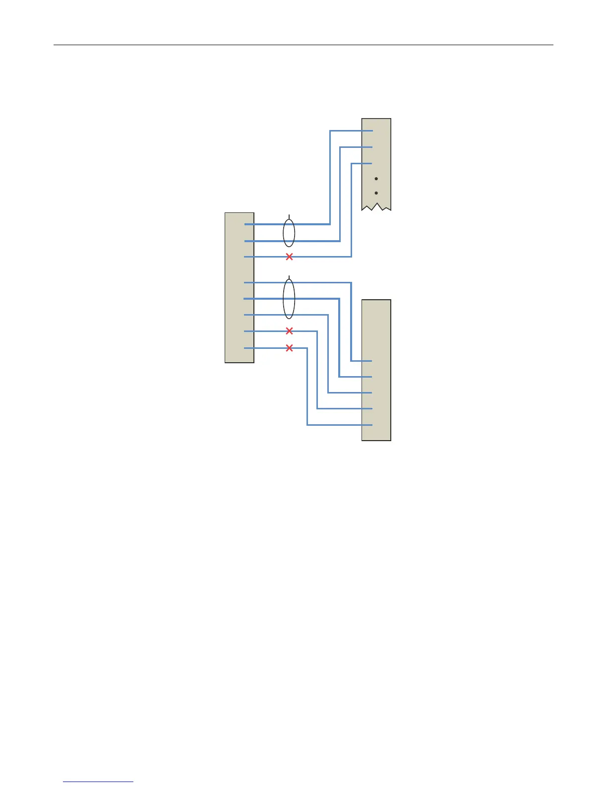
Figure 11-1 LAG Formation
Actor ports 1 - 3 on device A directly connect to partner ports 1 - 3 on device B:
• We have already stated that all ports are operating in full-duplex mode, so rule 1 is satisfied
for all three ports.
• Investigating the port admin keys, we see that ports 1 and 2 on device A are set to 100 (the
same setting as all LAG ports on the device), while port 3 on device A is set to 200. Because the
port admin keys are the same for both the LAG port and these physical ports, ports 1 and 2
satisfy rule 2. Because the admin key for physical port 3 is different from any possible LAG for
this device, port 3 can not be part of any LAG.
• Because ports 1 and 2 for both the actor and partner operate in parallel with each other, rule 3
is satisfied for these ports.
• Rule 4 is satisfied, regardless of whether single port LAGs are enabled, because there are two
aggregatable port pairings between devices A and B.
For these reasons, LAG 1 (lag.0.1) is formed using actor and partner ports 1 and 2.
Actor ports 4 - 8 on device A directly connect to partner ports 4 - 8 on device C:
• Because all ports are operating in full-duplex mode, rule one is satisfied for all five ports.
PARTNER
Port
Speed
Device
B
Device
A
Device
C
LAG 1
LAG 2
Admin
Key
ACTOR
Port
Speed
Admin
Key
100
100
100
100
100
100
100
100
100
100
100
100M
100M
100M
100M
100M
1Gb
1Gb
1Gb
100
100
200
100
100
100
300
400
100M
100M
100M
100M
100M
1Gb
1Gb
1Gb
100M
100M
100M
1
2
3
4
5
6
7
8
1
2
3
4
5
6
7
8
1
2
3

 Loading...


