STP Operation
Fixed Switch Configuration Guide 15-5
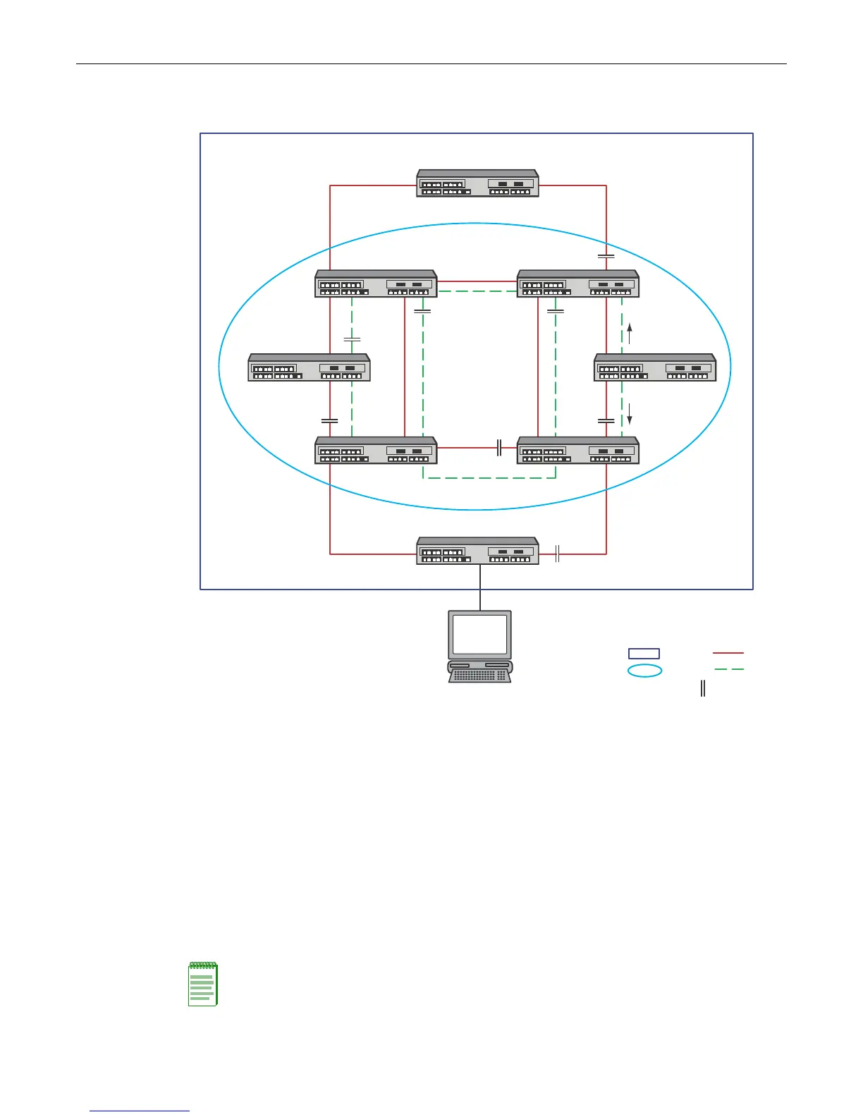
Figure 15-3 Multiple Spanning Tree Overview
SID 0 is the default Spanning Tree and interconnects all bridges to the Root Bridge. SID 0 within
the MST is the Internal Spanning Tree (IST) and provides connectivity out to the CST as well as
functioning as another Spanning Tree instance within the MST region. SID 1 is an MSTI
configured within the MST region.
Each SID has a root bridge. In Figure 15-3 the SID 0 root bridge belongs to the CST. The SID 0 root
bridge functions as root for SID 0 Spanning Tree instance in both the CST and MST. SID 1 only
exists within the MSTCentral region. The root for SID 1 is a bridge within the MSTCentral region.
SID 1 can provide traffic segmentation by forwarding traffic on a second VLAN within the
MSTCentral region or provide for optimization of redundant links by forwarding traffic within
the MSTCentral region on the same VLAN.
See “Configuring MSTP” on page 15-24 for examples of MSTP traffic segregation and
optimization of redundant links.
Note: MSTP and RSTP are fully compatible and interoperable with each other and with legacy STP.
CIST
Region
SID 0
Blocked Port
SID 1
S1 Root
ROOT Bridge
MST Region MSTCentral
MST Region Root
Non-Regional Bridge
Common and Internal Spanning Tree (CIST)
KEY:

 Loading...


