Configuring STP and RSTP
Fixed Switch Configuration Guide 15-19
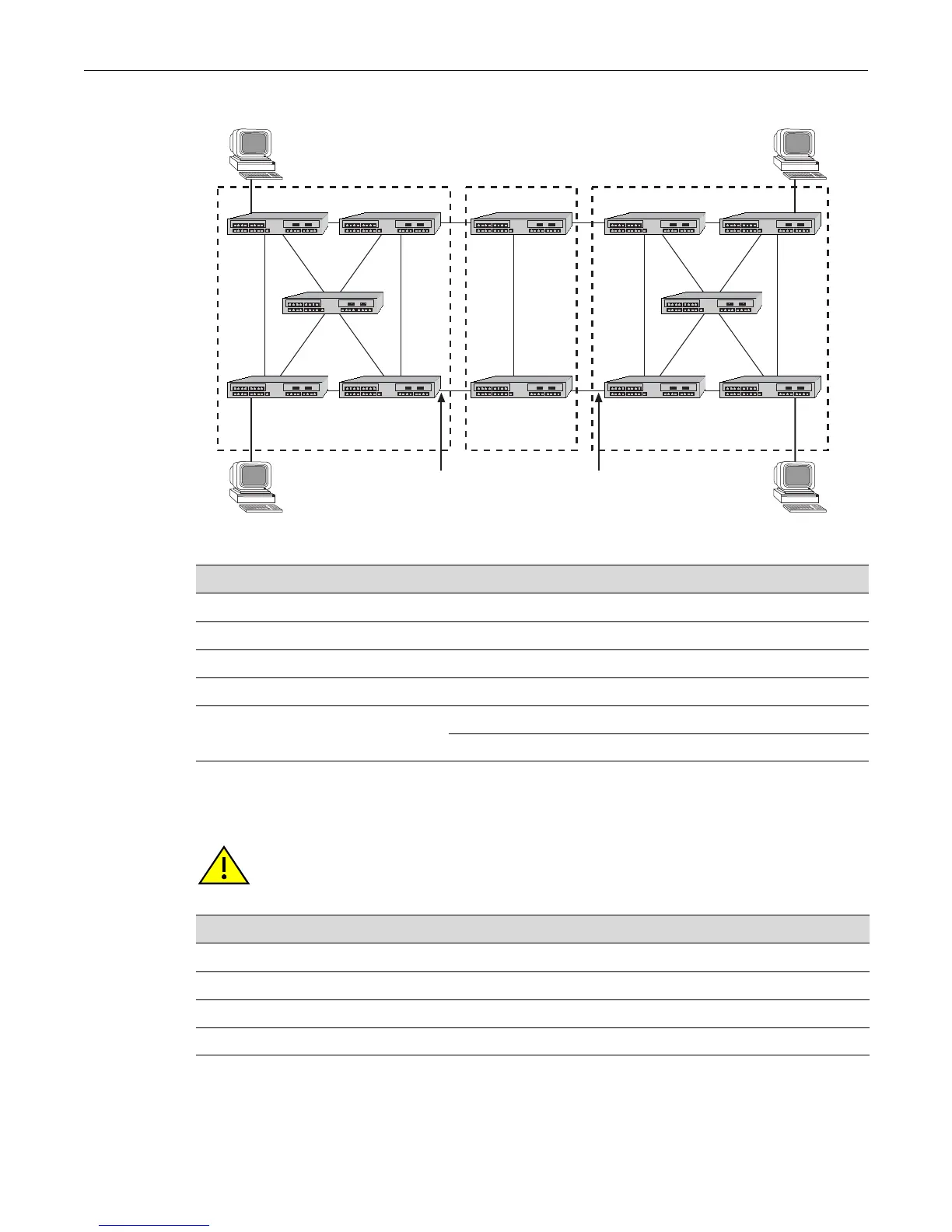
Figure 15-10 Example of Multiple Regions and MSTIs
Configuring STP and RSTP
Table 15-5 MSTI Characteristics for Figure 15-10
MSTI / Region Characteristics
MSTI 1 in Region 1 Root is switching device 4, which is also the CIST regional root
MSTI 2 in Region 1 Root is switching device 5
MSTI 1 in Region 2 Root is switching device 7, which is also the CIST root
MSTI 1 in Region 3 Root is switching device 11
MSTI 2 in Region 3
Root is switching device 12
Switching device 10 is the CIST regional root
Region 1
12
34
5
Region 3
89
10 11
12
Region 2
6
7
Master Port Master Port
CIST
Regional Root
CIST Root
and CIST
Regional Root
CIST
Regional Root
Caution: Spanning Tree configuration should be performed only by personnel who are very
knowledgeable about Spanning Trees and the configuration of the Spanning Tree Algorithms.
Otherwise, the proper operation of the network could be at risk.
For information about... Refer to page...
Reviewing and Enabling Spanning Tree 15-20
Adjusting Spanning Tree Parameters 15-20
Enabling the Backup Root Function 15-23
Adjusting RSTP Parameters 15-23

 Loading...


