Spanning Tree Basics
15-18 Configuring Spanning Tree
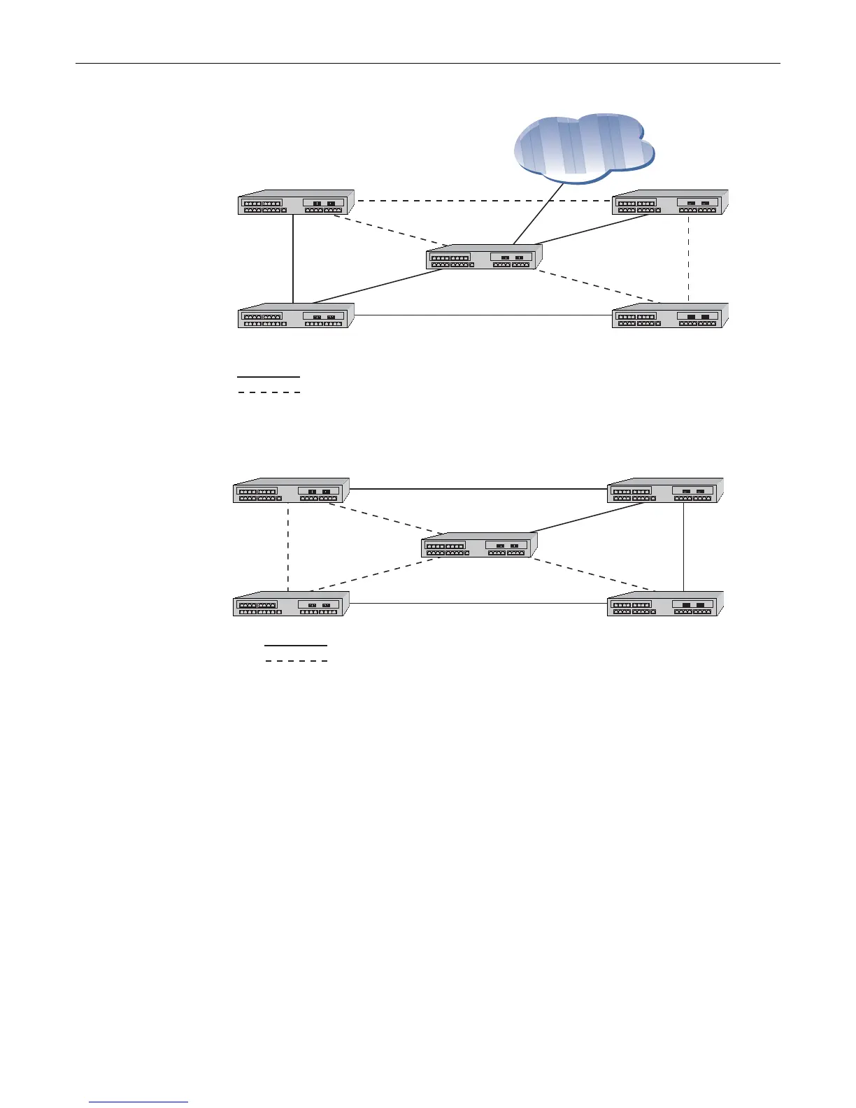
Figure 15-8 MSTI 1 in a Region
Figure 15-9 MSTI2 in the Same Region
Figure 15-10 on page 15-19 shows 3 regions with five MSTIs. Table 15-5 on page 15-19 defines the
characteristics of each MSTI. Ports connected to PCs from devices 1, 3, 9, and 11 will be
automatically detected as edge ports. Devices 4 and 10 are the CIST regional roots. Each MSTI can
be configured to forward and block various VLANs.
12
34
5
MSTI 1
MST CIST
Regional Root
MSTI 1 Regional Root
Physical Link
Legend:
Blocked VLANs
CIST Root
12
34
5
MSTI 2
MST CIST
Regional Root
MSTI 2
Regional
Root
Physical Link
Legend:
Blocked VLANs

 Loading...


