Spanning Tree Basics
Fixed Switch Configuration Guide 15-15
The MSTP enabled network may contain any combination of Single Spanning Tree (SST) regions
and Multiple Spanning Tree (MST) regions. A typical network may contain multiple MST regions
as well as separate LAN segments running legacy STP and RSTP Spanning Tree protocols. The
CIST contains a root bridge, which is the root of the Spanning Tree for the network. The CIST root
may be, but is not necessarily, located inside an MST region. Each MST region contains a CIST
regional root which may be the CIST root if the CIST root is internal to the region. If the CIST root
is external to the region, the CIST regional root provides the connectivity to the CIST root. Bridges
in an MSTP topology compare their received BPDUs to calculate their shortest path to the CIST
root, CIST regional root, and MSTI regional root.
Ideally, there should be one all-encompassing region. This is not always possible, for example,
when non-MSTP bridges exist such as those shown in Figure 15-3 on page 15-5. From the outside,
the region appears as a single Spanning Tree bridge which is part of the Common Spanning Tree
(CST). A port which connects to a bridge not having the same MST configuration ID, or which is
not running MSTP, forms part of the boundary of the region. The region attaches to the CST at the
root port of the CIST regional root. All other region boundary ports which provide paths to the
root are alternate ports and remain blocking until the topology changes, causing a new regional
root port to be chosen. Ports which provide a path to the root for other bridges at the region
boundary are designated ports. At boundary ports, port states for MSTIs follow the states of the
CIST for the port.
MST Region
An MST region is a group of devices that are configured together to form a logical region. The
MST region presents itself to the rest of the network as a single switching device, which simplifies
administration. Path cost is only incremented when traffic enters or leaves the region, regardless
of the number of devices within the region. Each LAN can only be a member of one region.
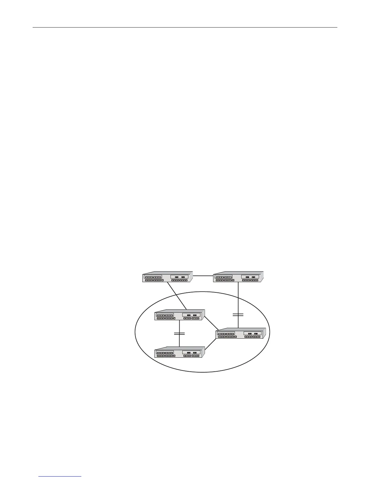
Figure 15-7 shows that the MST region appears as a single switching device to devices 1 and 2, but
really consists of three devices.
Figure 15-7 Example of an MST Region
For a switching device to be considered as part of an MST region, it must be administratively
configured with the same configuration identifier information as all other devices in the MST
region. The configuration identifier consists of four parts:
• Format Selector – One octet in length and is always 0. It cannot be administratively changed.
• Configuration Name – A user-assigned, case sensitive name given to the region. The
maximum length of the name is 32 octets. A bridge’s default configuration name is a character
MST Region
Device 1 Device 2

 Loading...


