Configuring OSPF Areas
Fixed Switch Configuration Guide 22-13
The virtual-link is treated as if it were an unnumbered point-to-point network belonging to the
backbone and joining the two ABRs. The cost of a virtual link is not configured. It is auto
configured with the cost of the intra-area path between the two ABRs that make up the virtual-
link.
Use the area virtual-link command in OSPF router configuration command mode, providing the
transit area ID and the ABRs router ID, to configure an area virtual-link.
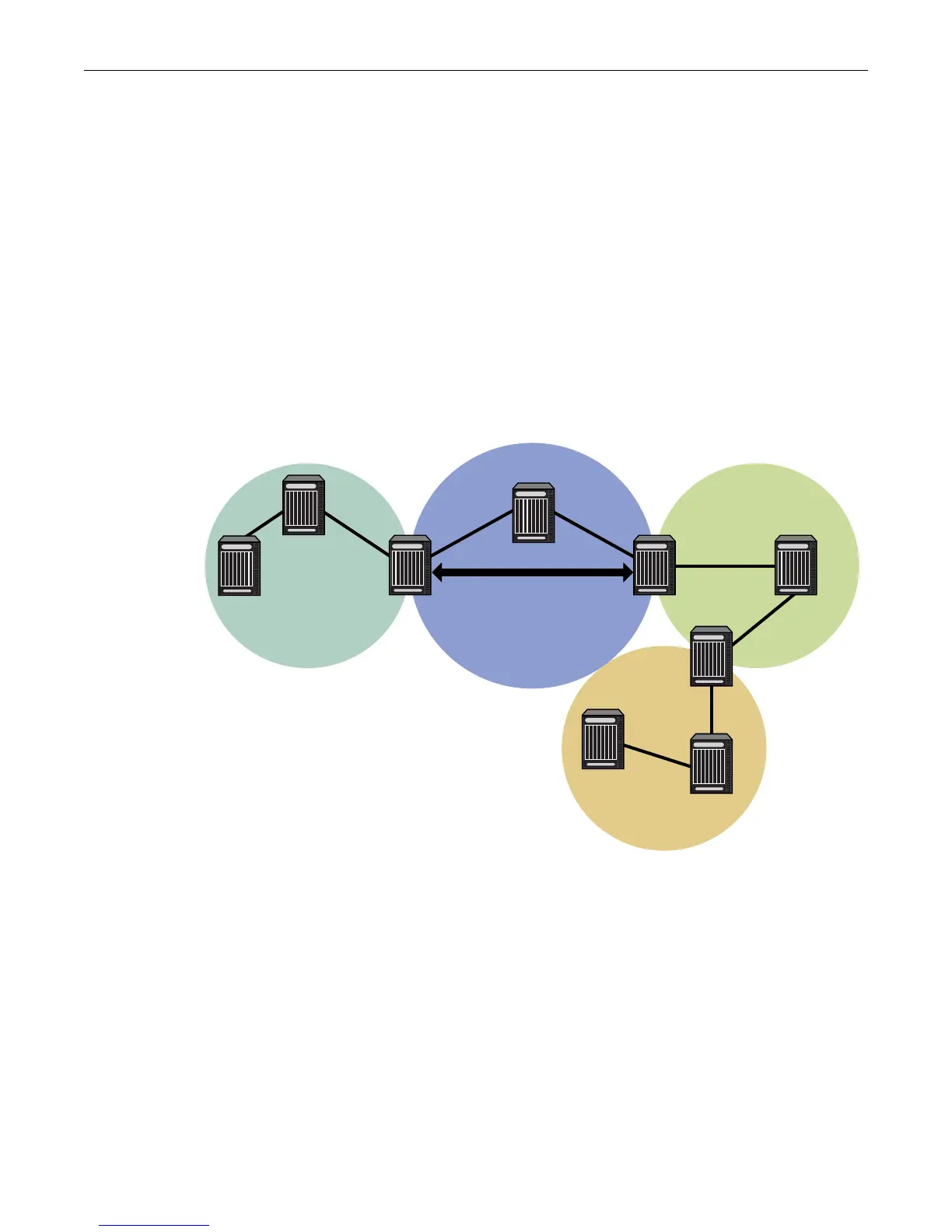
Figure 22-6 on page 22-13 displays a typical virtual-link topology. Area 3 does not share an ABR
with the backbone area, and is therefore disconnected from the backbone. Area 3 shares an ABR
(router 2) with area 1. Area 1 has a second ABR (router 1) that it shares with the backbone. Area 1
is the transit area because it contains an ABR that it shares with the disconnected area and a
second ABR that it shares with the backbone. By configuring an area virtual-link between router 2
and router 1, Area 3 will gain connectivity with the backbone and be able to learn routes for this
AS.
Example
Figure 22-6 Virtual Link Topology
The following code example presents the configuration required to configure the virtual-link
displayed in Figure 22-6:
Router 1
Router 1(su)->router(Config)#router id 1.1.1.1
Router 1(su)->router(Config)#router ospf 1
Router 2(su)->router(Config-router)#area 0.0.0.1 virtual-link 2.2.2.2
Router 2
Router 2(su)->router(Config)#router id 2.2.2.2
Router 2(su)->router(Config)#router ospf 1
Router 2(su)->router(Config-router)#area 0.0.0.1 virtual-link 1.1.1.1
Backbone
Area 3
Virtual Link
Area 1
Area 2
Router 2
Router ID = 2.2.2.2
Router 1
Router ID = 1.1.1.1

 Loading...


