Introduction
RF IN
ASI OUT 1-2 CVBS
ETHERNET 1-2ALARM
AUDIO OUT 1-2
TECHNICAL EARTH
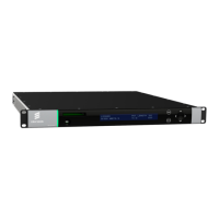
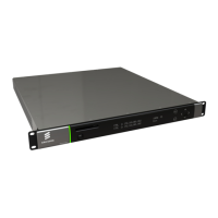
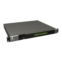
Figure 1.9 Rear Panel (RX8305)
Table 1.15 Rear Panels
Item Type Description
RF IN 1-4
F-type 75 Ω
Radio Frequency (L-band) input.
ASI OUT 1-2
ASI/SDI OUT
ASI/HD-SDI/SD-SDI
OUT
ASI/3G-SDI/HD-
SDI/SD-SDI OUT
BNC 75 Ω
ASI = Asynchronous Serial Interface.
SDI = Serial Digital Interface.
SD-SDI = Standard Definition SDI.
HD-SDI = High Definition SDI.
3G-SDI = 2.970 Gbps serial link required for
1080P support.
CVBS
BNC 75 Ω
Composite Video output.
ASI INPUT
BNC 75 Ω
Asynchronous Serial Interface input.
Streaming data format that carries the MPEG
Transport Stream.
SVGA OUTPUT 15-way D-type Component Video output (RGB/HV (SVGA) or
YPrPb).
IP DATA 1-2 RJ-45 IP Output card supports 1000BaseT Ethernet
transmission of encapsulated transport stream
ETHERNET 1-2
CONTROL 1-2
RJ-45 10-100BaseT control port for HTTP and FTP
control of the RX8000.
ALARM
ALARM RELAY
9-way D-type A summary ALARM relay provides contact
closure when the unit detects an alarm, or the
power is switched off.
AUDIO OUT 1-2 9-way D-type Each connector carries a single channel of a
stereo pair in both analogue and balanced
digital form.
CA INTERFACE Card Slot A single slot allows the insertion of a
Conditional Access Module (CAM) for
Common Interface support. On the RX8330C
this will be replaced with a smartcard slot.
AC POWER IEC 100-240 V AC power input.
TECHNICAL EARTH Spade terminal Unit earthing connector.