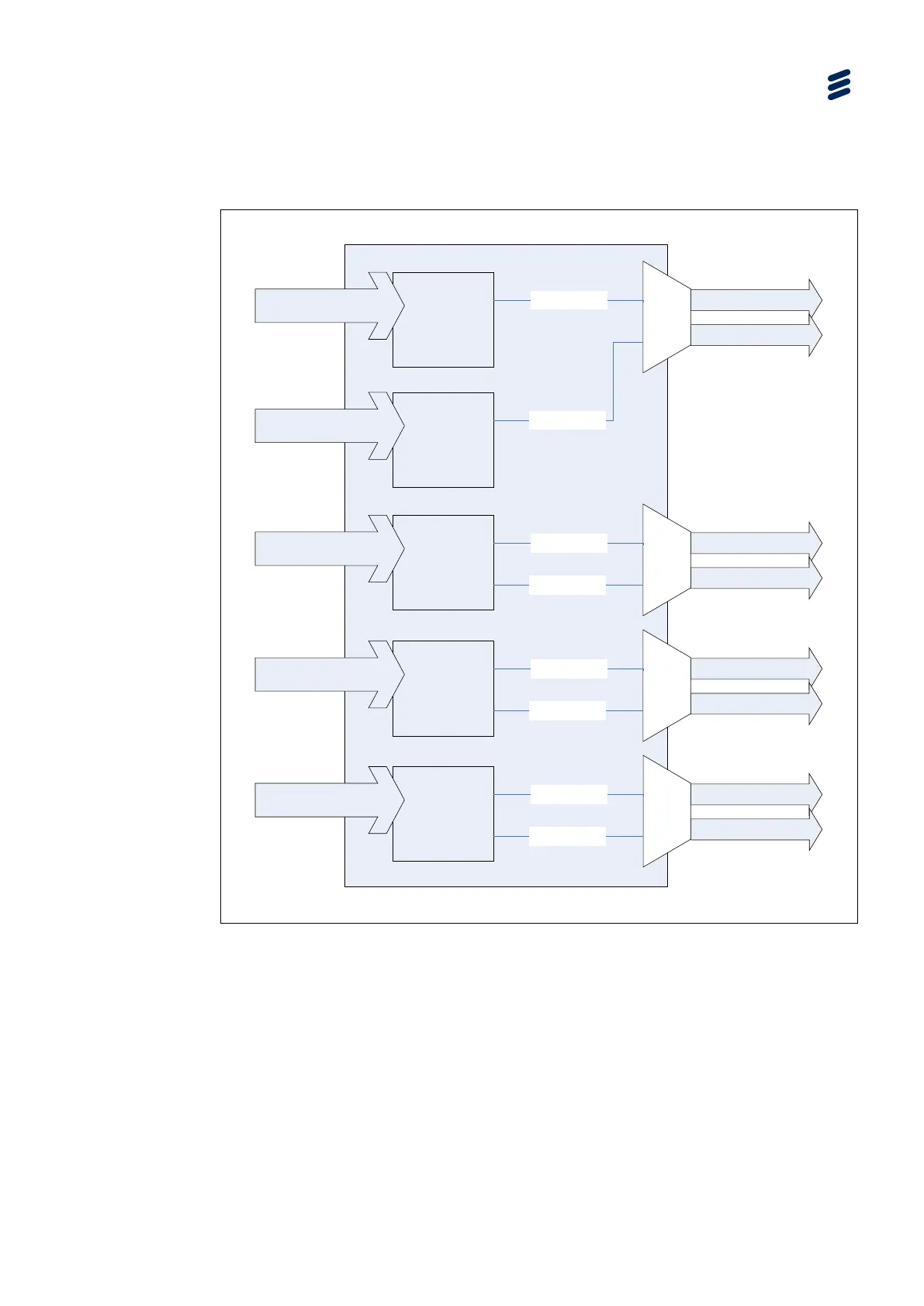
Using the Equipment
The diagram above illustrates four Audio Decoders each configured to output two
channels and assigned to an audio output port. Where the decoded audio stream is
mono, it is output on both channels.
Audio
Decoder
1R
Audio ES
Channel 1
Audio
Decoder 2
Audio ES
Audio
OUT 2
Left
Right
Channel 1
Channel 2
Audio
Decoder 3
Audio ES
Audio
OUT 3
Left
Right
Channel 1
Channel 2
Audio
Decoder 4
Audio ES
Audio
OUT 4
Left
Right
Channel 1
Channel 2
Audio
Decoder
1L
Audio ES
Audio
OUT 1
Left
Right
Channel 1
Figure 3.122 Configuration for Audio Decoder Pairing
The diagram above illustrates how Audio Decoder 1 has been paired with another
decoder to produce Audio Decoder 1L and 1R. Audio Decoder 1L and 1R are then
configured to output one channel each. This allows two separate audio streams to
be decoded separately but paired together to provide a dual-mono output on the
associated audio output port. Where the decoded audio stream is stereo, it will be
down-mixed to a single mono channel.
Note: In this mode there will only ever be eight output channels after enabling the
RX8200/SWO/4AUD license.