Dynamic Modulation Sources (Dmod) Dynamic Modulation Source List
595
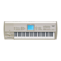
Gate1, Gate1+Dmpr (Gate1, Gate1+Damper)
The effect is at maximum during note-on, and will stop
when all keys are released. With Gate1 + Damper, the effect
will remain at maximum even after the keys are released, as
long as the damper (sustain) pedal is pressed.
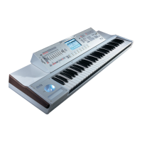
Gate2, Gate2+Dmpr (Gate2, Gate2+Damper)
This is essentially the same as for Gate 1 or Gate 1 + Dmpr.
However when Gate 2 or Gate 2 + Damper are used as a
dynamic modulation source for the EG of 034: St. Env.
Flanger etc. or the AUTOFADE of 038: Stereo Vibrato, a
trigger will occur at each note-on. (In the case of Gate 1 and
Gate 1 + Dmpr, the trigger occurs only for the first note-on.)
Exp Velocity (Exponential Velocity)
Modulation will be applied exponentially according to the
velocity value. Weak velocity values will produce little
effect, but the effect will increase rapidly as the velocity
values rise.
Pedal: #04 (Foot Pedal: CC#04)
If you wish to use the assignable foot pedal as a dynamic
modulation source, set “Foot Pedal Assign” (Global P2:
Controller 2–1a) to Foot Pedal (CC#04). (See “Foot Pedal
Assignments” on page 600)
A foot controller etc. connected to the ASSIGNABLE PEDAL
jack can be used to control an effect.
ValSldr: #18 (Value Slider: CC#18)
When Program mode P0: Play– Main “Program Select” or
Combination mode P0: Play– Main “Combination Select”
are selected, the VALUE slider will function as a controller
corresponding to CC#18.
SldrM5: #17 (Slider Modulation5: CC#17)
SldrM6: #19 (Slider Modulation6: CC#19)
SldrM7: #20 (Slider Modulation7: CC#20)
SldrM8: #21 (Slider Modulation8: CC#21)
If you want to use Realtime Control Slider 5–8 as AMS, set
the Controllers Setup page “Realtime Control Slider Assign”
parameters to assign “Slider5” to Slider Mod.5 (CC#17),
“Slider6” to Slider Mod.6 (CC#19), “Slider7” to Slider Mod.7
(CC#20), and “Slider8” to Slider Mod.8 (CC#21) (see
“Realtime Control Slider 5–8 Assignments” on page 598) for
each program, combination, song, or for Sampling mode.
You can control the effect by operating Realtime Control
Slider 5–8.
If the slider is set to the center position, the resulting effect
as a dynamic modulation source will be zero. If the
“Amount” is a positive (+) value, raising the slider will
apply positive change, and lowering it will produce
negative change. (With negative values, the result will be the
opposite.)
SldrM5 [+] (Slider Modulation5 [+])
SldrM6 [+] (Slider Modulation6 [+])
SldrM7 [+] (Slider Modulation7 [+])
SldrM8 [+] (Slider Modulation8 [+])
The slider position and the direction of the resulting change
are different than Slider Mod5 (CC#17)–Slider Mod8
(CC#21). If “Amount” is set to a positive (+) value, the result
as a dynamic modulation source will be zero when the slider
is lowered all the way. Raising the slider all the way will
apply change only in the positive direction. (If the
“Amount” is set to a negative value, the result will be the
opposite.)
SW 1: #80 (Switch Modulation 1: CC#80)
SW 2: #81 (Switch Modulation 2: CC#81)
If you wish to use the SW1 or SW2 switch as a dynamic
modulation source, make settings in Program, Song, or
Sampling modes to set the Controllers Setup page
parameter Panel Switch Assign to the following values
respectively: “SW1” to SW1 Mod. (CC#80), or “SW2” to SW2
Mod. (CC#81) (“SW1/2 Assignments” on page 597).
The effect will be controlled when you operate the SW1 or
SW2 switch.
FootSW: #82 (Foot Switch: CC#82)
If you wish to use an assignable foot switch as a dynamic
modulation source, set Foot Switch Assign (Global 2–1a) to
Foot SW (CC#82) (“Foot Switch Assignments” on page 599).
The effect will be controlled when you operate a foot switch
etc. connected to the ASSIGNABLE SWITCH jack.
XY +X: #85 (X–Y Mode Modulation +X: CC#85)
XY –X: #86 (X–Y Mode Modulation –X: CC#86)
XY +Y: #87 (X–Y Mode Modulation +Y: CC#87)
XY –Y: #88 (X–Y Mode Modulation –Y: CC#88)
If you want to use the X–Y control as a dynamic modulation
source, go to the X–Y CC Control page for each program,
combination, or song, and set the X–Y CC Control
parameters “+X,” “–X,” “+Y,” and “–Y” respectively to XY
+X Mod. (CC#85), XY –X Mod. (CC#86), XY +Y Mod.
(CC#87), and XY –Y Mod. (CC#88). (If “X Mode” or “Y
Mode” is Positive or Negative, you’ll be able to use either +
or –, not both.)
Modulation will be applied when you turn on X–Y MODE
and operate X–Y control.
X–Y CC Control “+X,” “–X,” “+X” and “–Y” settings can be
made in the Prog P1– X–Y Setup page and in the Combi/Seq
P1– X–Y CC T01–08/T09–16 page.
Note: Dynamic modulation via the X–Y Mode is not
available in Sampling mode.
Tempo
The resulting modulation will be zero at 120 BPM, the
maximum positive value at 240 BPM, and the maximum
negative value at 60 BPM.
Gate1,Gate1+Dmpr
Gate1
Note
Dmpr
1
2
3
1
2
3
Damper Pedal
Gate1+Dmpr
Time
On
Off
Gate2,Gate2+Dmpr
Gate2
Note
Dmpr
1
2
3
1
2
3
Damper Pedal
Gate2+Dmpr
Time
On
Off
 Loading...