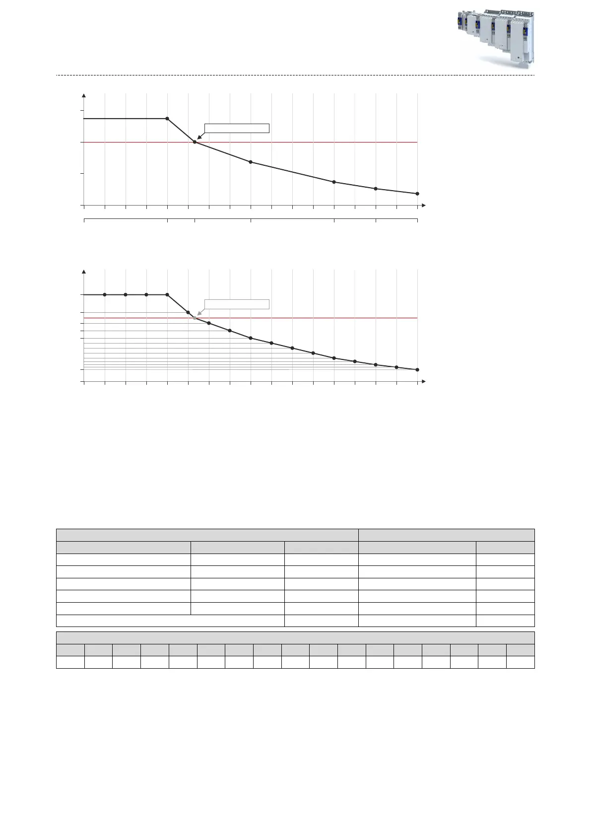
15 A7.5 A3.75 A 11.25 A 12.38 A5 A
0 6.25 12.5 18.75 25 31.25 37.5 43.75 50 56.25 62.5 68.75 75 81.25 87.5 93.75 100
Vp [%]
0 A
0
100
I
max
[%]
x2 x3 x4 x5 x6 x7 x8 x9 x10 x11 x12 x13 x14 x15 x16 x17x1
Vp = "3.8 V/A" 100 %º
50
150
7.
En
ter the percentage Vp values of the grid points into the subindices
(0x2C04:001 ... 0x2C04:017):
0 6.25 12.5 18.75 25 31.25 37.5 43.75 50 56.25 62.5 68.75 75 81.25 87.5 93.75 100
I
max
[%]
Vp [%]
0
109
x2 x3 x4 x5 x6 x7 x8 x9 x10 x11 x12 x13 x14 x15 x16x1
19
137
x17
Vp = "3.8 V/A" 100 %º
92
80
68
See table
"Seng of grid point 1 ... 17 in [%]" aer this lisng
8.
En
ter the maximum process current ("15 A") in 0x6073 as the maximum current.
•
The sengs made should now cause the same basic current characterisc irrespecve
of the current level.
•
No
w that the current controller gain is acvely corrected, the step responses may
slightly dier from the previous measurements. In this case, the current controller
parameters must be post-opmised for the last me.
9.
F
or permanent storage: save the characterisc determined.
The »E
ASY Starter« serves to save the parameter sengs of the inverter as parameter le
(*.gdc). Saving the parameter sengs
Specicaons for adjustment Measured values
Grid point Scaling Current setpoint Vp [V/A] Tn [ms]
5 0.25 * 15 A = 3.75 A 5.2 6.5
9 0.5 * 15 A = 7.5 A 2.6 4
13 0.75 * 15 A = 11.25 A 1.4 2.5
15 0.875 * 15 A = 12.38 A 1.0 2
17 1.0 * 15 A = 15 A 0.7 1.7
Rated motor current= 5 A 3.8 5
Seng of grid point 1 ... 17 in [%]
y1 y2 y3 y4 y5 y6 y7 y8 y9 y10 y11 y12 y13 y14 y15y y16 y17
137 137 137 137 137 109 92 80 68 61 53 45 37 32 26 22 19
Conguring the motor control
Fine adjus
tment of the motor model
Correcon of the stator leakage inductance (Lss)...
278