Proceeding
1.
Deacvate
correcon: Set all subindices (0x2C04:001 ... 0x2C04:017) to 100 %.
2.
Use 0x2C05 to set the maximum current up to which the motor is to be operated in the
process (in this example "15 A").
3.
Adjust the current controller with dierent current setpoints by means of the manual test
mode Manual "curr
ent pulse" test mode and take down the corresponding sengs for Vp
and Tn.
•
The procedure is described in secon Manual "current pulse" test mode.
•
The current setpoints to be set for the corresponding adjustment in object 0x2835:001
result from the scaling of the maximum process current to the X axis of the saturaon
characterisc.
•
The grid poin
ts which are required to dene the saturaon characterisc with a su-
cient quality varies from motor to motor and thus has to be determined individually.
•
F
or this example, currents that are part of the grid points 5, 9, 13, and 15 have been
selected, and a measurement at rated motor current was carried out addionally:
15 A7.5 A3.75 A 11.25 A 12.38 A5 A
0 6.25 12.5 18.75 25 31.25 37.5 43.75 50 56.25 62.5 68.75 75 81.25 87.5 93.75 100
0 A
I
max
[%]
Vp [V/A]
Tn [ms]
x2 x3 x4 x5 x6 x7 x8 x9 x10 x11 x12 x13 x14 x15 x16 x17x1
See table "Specicaons for adjustment / measured values" aer this lisng
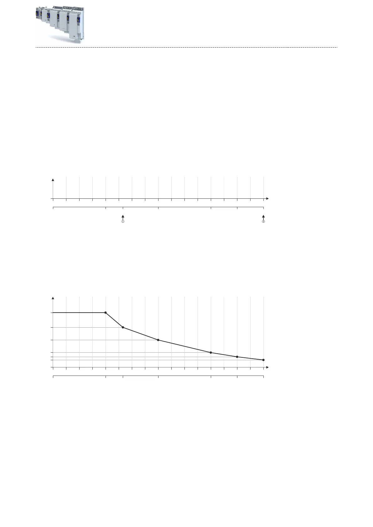
4.
Cr
eate a characterisc based on the detected values for Vp (but do not enter any values in
y
et).
•
Determine the values of the grid points that have not been adjusted by interpolaon
between two values.
•
Note: This example assumes that the inductance does not change considerably below
3.75 A. For this reason, the same Vp value that resulted from the measurement with a
motor current of 3.75 A was used for all grid points below 3.75 A.
15 A7.5 A3.75 A 11.25 A 12.38 A5 A
0 6.25 12.5 18.75 25 31.25 37.5 43.75 50 56.25 62.5 68.75 75 81.25 87.5 93.75 100
Vp [V/A]
0 A
0
1.0
1.4
2.6
3.8
5.2
I
max
[%]
x2 x3 x4 x5 x6 x7 x8 x9 x10 x11 x12 x13 x14 x15 x16 x17x1
0.7
5.
Se
t gain Vp and reset me Tn to the values that were determined during the adjustment
with the r
ated motor current (in this example "5 A"):
•
0x2942:001 is set to "3.8 V/A".
•
0x2942:002 is set to "5 ms".
6.
Scale Vp values on the Y axis of the characterisc to the Vp seng "3.8 V/A":
Conguring the motor control
Fine adjus
tment of the motor model
Correcon of the stator leakage inductance (Lss)...
277