6. The bearer terminal process selects an OFI and a port for the
call. The bearer terminal process requests that the OFI open the
selected port for this transaction. Finally, the IP address and port
number of the selected resource are forwarded to the SIP terminal
process.
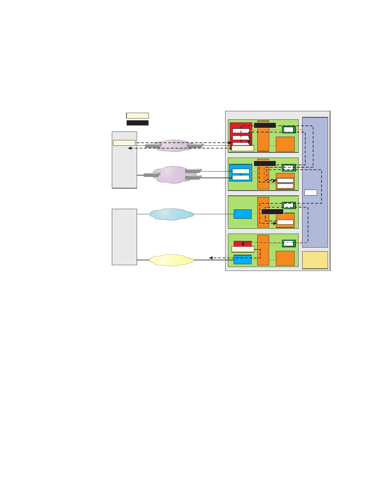
7. The SIP terminal process creates a 183 SESSION PROGRESS
message. This message is in a compact, internal SIP format. This
message contains the IP address and port for the terminating
bearer resource. The SIP message is forwarded to the SIP PH in
the SIP GSM.
8. The SIP PH expands the 183 SESSION PROGRESS message to
standard external SIP format, adds the appropriate SCTP and IP
headers, and forwards it to OPS via the IP signaling network.
9. The SIP terminal process passes notification to the ISUP terminal
process. An ISUP IAM message is created and forwarded to the
ST PH in the SS7 GSM. Finally, the message is sent to the
terminating switch.
10. The TPS waits for the OPS to respond.
Figure 3-23 Call Setup at TPS - Steps 7-12
OIU
SDL
Ethernet
IP Network
OC-3c
IP Network
OC-3c
SONET
Originating
Packet
Switch
(OPS)
Terminating Packet Switch (TPS)
AM
NLI
PSU
DLTU
SM-2000
TSI
SMP
NLI
SM-2000
SMP
PSU
GQPH
SIP-PH
PSUCOM
TSI
NLI
SM-2000
SMP
TSI
OFI-IP
OFI-IP
BRR TP
SIP TP
NLI
DNUS
SM-2000
TSI
SMP
ISUP TP
CM
CMP
Terminating
Switch
PSTN
CCS-SS7
7
8
Message
Message
In a standard, external format
In a compact, internal format
183
UPDATE
11
183
9
ISUP IAM
ISUP IAM
9
9
UPDATE
12
SIP without Encapsulated ISUP - Detailed
Call Scenario
Call Flow
....................................................................................................................................................................................................................................
3-58
Lucent Technologies 235-200-118
Issue 3.02B, March 2007