Refer to Table 4-4, “PH equipage - one shelf” (4-7) for a suggested
equipage. This equipage spreads the PH packs across power buses and
fuse groups. It also provides efficient circuit pack cooling.
Note: This table provides equipage for the first eight PHs, when
additional PHs are equipped in the shelf, the pattern is expanded to
include the remaining slots.
Table 4-4 PH equipage - one shelf
Number of PHs Horizontal EQL
1 062
2 062, 128
3 062, 128, 030
4 062, 128, 030, 160
5 062, 128, 030, 160, 046
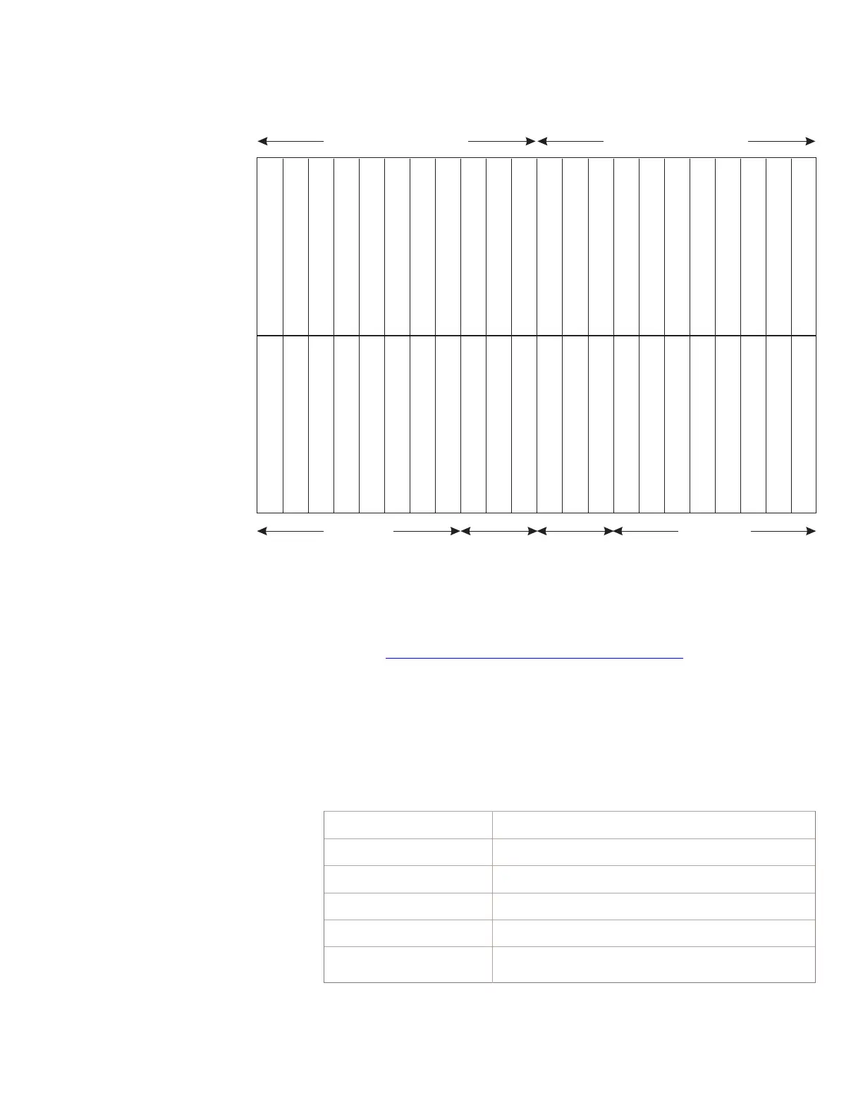
Figure 4-1 Two shelf PSU2
PH Slots PH Slots
PSUCOM 0
006 014
022
030 038
046 054 062 070 078 088 100 110 120 128
136
144
152 160 168 176 184
EQL
PH Slot
Number
0
12
3
4
5
6
7
8910
11 12
13
14
15
PSUCOM 1
Power Bus - A Power Bus - B
C
F
2
*
C
F
2
*
P
F
2
P
F
2
D
F
2
D
F
2
* Note: the CF2 packs are located in the basic shelf only.
006 014
022
030 038
046 054 062 070 078 088 100 110 120 128
136
144
152 160 168 176 184
PH Slot
Number
0
12
3
4
5
67 8910
11 12
13
14
15
P
F
2
P
F
2
D
F
2
D
F
2
Shelf 0
(Basic)
Shelf 1
Packet Switch Unit Model 2 (PSU2)
Considerations
Engineering Considerations
....................................................................................................................................................................................................................................
235-200-118
Issue 3.02B, March 2007
Lucent Technologies
4-7