Packet Trunking
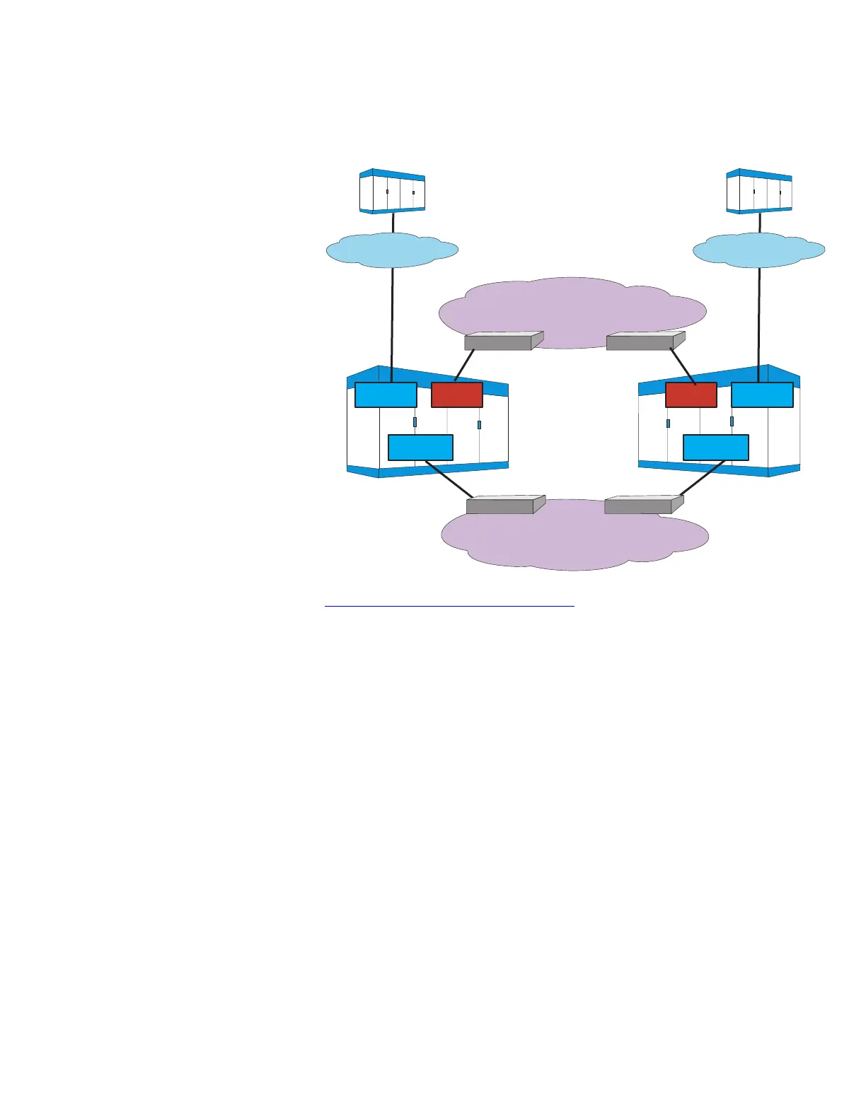
Figure 2-5, “Packet Trunking” (2-7) illustrates a packet trunking
network. In this network, 5ESS
®
switches connect to IP switches and
IP routers connected in order to provide end-to-end routing of
information. An end office (EO), the 5ESS
®
switch, connects to an
edge router to access the IP network. The two packet offices shown
are 5ESS
®
switches; however, either can be other vendor switches as
long as they support IP packet trunking with SIP signaling. An
Ethernet link connects the PSU2 to an edge router to provide the
signaling path. A Synchronous Optical Network (SONET) optical
carrier - level 3 concatenated (OC-3c) link connects the OIU-IP and
the router for the voice path.
Calls using packet trunking are dynamically allocated to available
packet network interface bandwidth each time a call is established,
whereas calls using time division multiplexing (TDM) trunking are
assigned to circuits or connections dedicated to two endpoints. In
packet trunking, call and connection information is exchanged using
SIP signaling and voice packets are transmitted, routed and received
Figure 2-5 Packet Trunking
IP Bearer Network
OC-3cOC-3c
IP Signaling Network
Edge RouterEdge Router
Ethernet Ethernet
OPS
PSU2
OIU-IP
PSU2
OIU-IP
TPS
DNU-S DNU-S
Edge Router Edge Router
PSTN
Originating Switch
PSTN
Terminating Switch
Network View
Architecture
....................................................................................................................................................................................................................................
235-200-118
Issue 3.02B, March 2007
Lucent Technologies
2-7