over a single physical network. Figure 2-1, “IP Backbone” (2-3)
illustrates one common network. Figure 2-5, “Packet Trunking” (2-7)
illustrates distinct networks.
Signaling Network
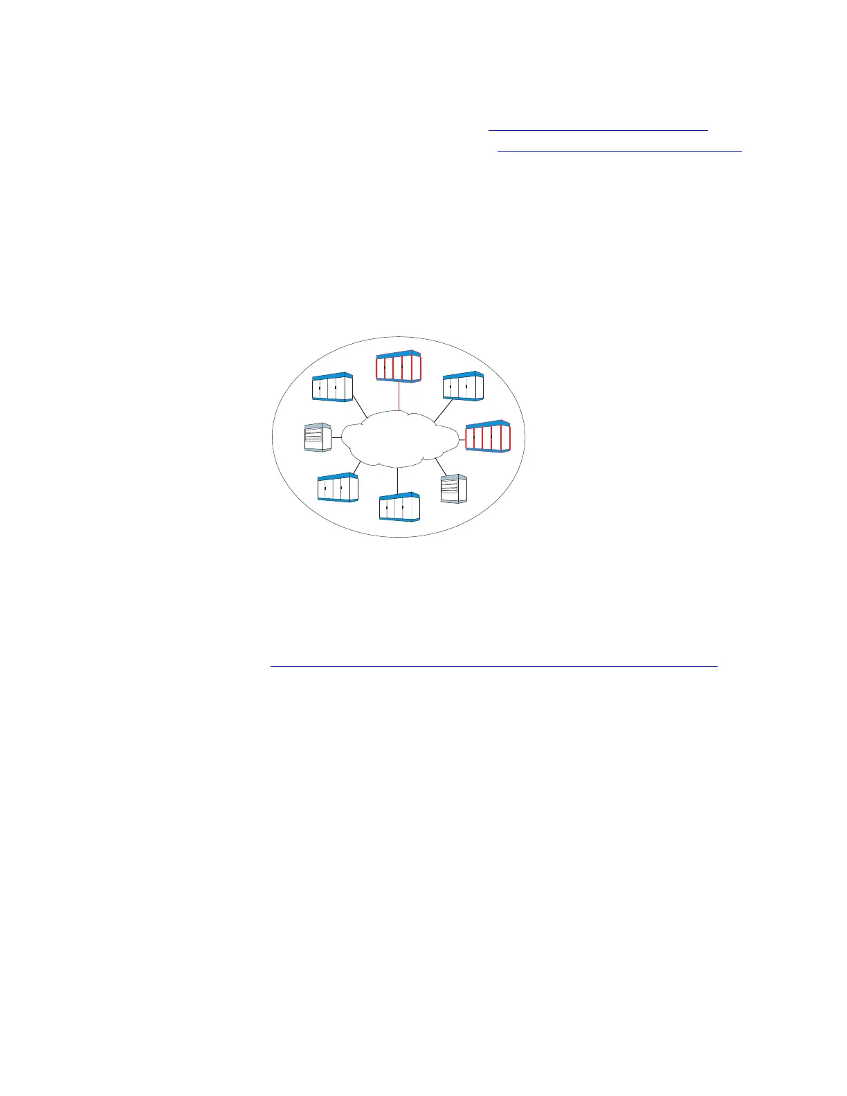
From a hardware perspective, each network element, such as end
offices (EO), EO-local tandems (LT), and EO-access tandems (AT), in
the SIP signaling network is connected to the IP network. Signaling
messages between network element are dynamically routed by the IP
network.
Figure 2-2, “SIP Signaling Network, Hardware Perspective” (2-4)
shows the signaling network for an IP network using SIP from a
Figure 2-2 SIP Signaling Network, Hardware Perspective
EO = End Office
AT = Access Tandem
LT = Local Tandem
TAS = Telephone Application
Server
AT
EO
LT
EO
EO
EO
IP Network
TAS
TAS
Network View
Architecture
....................................................................................................................................................................................................................................
2-4
Lucent Technologies 235-200-118
Issue 3.02B, March 2007