11. The SIP PH receives and accepts an UPDATE message from the
OPS. The message informs the TPS that the OPS has opened the
upstream port and that the bearer path is now available.
12. The SIP PH strips the SCTP and IP headers, compacts the
message to the internal SIP format, and forwards the message to
the SIP terminal process.
13. The SIP PH builds the 200 OK (UPDATE) message in standard,
external SIP format, adds the appropriate SCTP and IP headers,
and forwards it to OPS via the IP signaling network.
14. The SIP terminal process passes the updated call state to the
ISUP terminal process. An ISUP COT message is formulated and
forwarded to the ST PH in the SS7 GSM. Finally, the message is
sent to the terminating switch.
15. An ISUP ACM message arrives at the TPS on a signaling data
link (SDL). The message is sent from the trunk peripheral
terminating the SDL to the ST PH in the SS7 GSM via nailed up
timeslots.
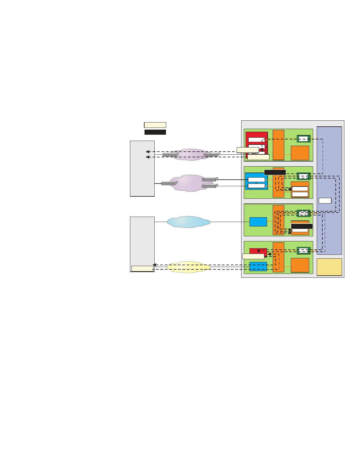
Figure 3-24 Call Setup at TPS - Steps 13-18
OIU
SDL
Ethernet
IP Network
OC-3c
IP Network
OC-3c
SONET
Originating
Packet
Switch
(OPS)
Terminating Packet Switch (TPS)
AM
NLI
PSU
DLTU
SM-2000
TSI
SMP
NLI
SM-2000
SMP
PSU
GQPH
SIP-PH
PSUCOM
TSI
NLI
SM-2000
SMP
TSI
OFI-IP
OFI-IP
BRR TP
SIP TP
NLI
DNUS
SM-2000
TSI
SMP
ISUP TP
CM
CMP
Terminating
Switch
PSTN
CCS-SS7
18
Message
Message
In a standard, external format
In a compact, internal format
OK UPDATE
14
ISUP COT
ISUP COT
14
14
ISUP ACM
15
16
16
17
180 RING
13
180 RING
SIP without Encapsulated ISUP - Detailed
Call Scenario
Call Flow
....................................................................................................................................................................................................................................
235-200-118
Issue 3.02B, March 2007
Lucent Technologies
3-59