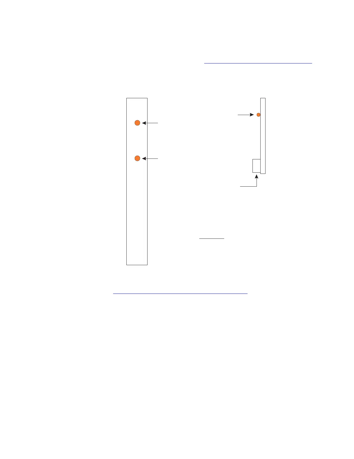
Ethernet cable. At the bottom of the paddle board there is a connector
for the Ethernet cable. Refer to Figure 2-14, “Pack Faceplates” (2-26).
PSU2 shelf arrangement
Figure 2-15, “PSU2 Shelf Arrangement” (2-27) provides the general
layout of a PSU2 shelf. The shelf shown is the common shelf (shelf
0). A fully equipped PSU2 consists of five shelves; the common shelf
and four growth shelves.
Figure 2-14 Pack Faceplates
OOS LED
SF LED
SF LED
Ethernet
Termination
Legend:
OOS - Out of Service
SF - Signal Fail
LLE2 Paddle Board
SIP PH & GQPH
Circuit Packs
Hardware View
Architecture
....................................................................................................................................................................................................................................
2-26
Lucent Technologies 235-200-118
Issue 3.02B, March 2007